Overview
Abstract
The Anesthesia Model is a generic representation of mechanical ventilation and inhaled agent administration. It models a semi-closed circuit breathing system. The Anesthesia System employs a pressure-control ventilation mode for positive-pressure ventilation and gas delivery. The model uses a constant ventilator pressure source to drive inspiration and release pressure during expiration. This model provides an important system required for the training and simulation of a complex medical field. A variety of common equipment failures associated with anesthesia machines are available with this system. The results of this system were qualitatively evaluated for all common failures modeled. The results show an excellent correlation with the expected trends. Future work will address the current limitations of the system and development of a more robust Anesthesia Machine.
Introduction
Anesthesia Machines and Positive-Pressure Ventilation
An anesthesia machine is used to both control a patient's gas exchange through mechanical ventilation, or positive-pressure ventilation, and administer inhaled anesthetic agents. These machines are highly sophisticated, and they require training and problem-solving skills for appropriate use and avoidance of user- and equipment-related failures. While there are relatively few companies manufacturing anesthesia machines, there is a large variety in models and types of machines. This provides a wide range of complexity and functionality that can be chosen based on the facilities' expectations and requirements. The administration of anesthesia also requires the delivery of multiple drugs that are chosen based on the individual patient's condition and the procedure type and duration. The combination of equipment and drug administration makes anesthesiology a difficult discipline that requires significant training to avoid failures that could lead to patient injury or death. [320] [127]
In general, anesthesia machines contain the following basic components [320] [127] :
- Compressed gas cylinders - These contain oxygen and/or nitrogen for portable use with the machine. Oxygen may also be supplied through a wall port.
- Vaporizer - Inhaled agents are inserted into the machine in liquid form and must be aerosolized for patient administration.
- Unidirectional valves - Valves open and close during the inspiratory and expiratory cycles to prevent rebreathing of carbon dioxide.
- Carbon dioxide absorber - Carbon dioxide is scrubbed from the anesthesia machine circuit using different absorbers.
- Ventilator - The bellows supplies gas flow to the patient.
- Tubing - All equipment is connected through tubing that can become tangled or develop leaks if not monitored regularly.
Airway management is also associated with a number of components that provide air to the patient depending on the patient's condition and surgery specifics. These components include the following [347] :
- Mask - A mask can be placed on the patient's face to supply supplemental oxygen or an inhaled anesthetic.
- Endotracheal tube (ETT) - This tube can be placed in the trachea through the intubation process for positive-pressure ventilation for a fully sedated patient. These come in a variety of styles and sizes that must be chosen based on the patient.
- Laryngeal Mask Airway (LMA) - This device has become common for patients with a difficult airway. It combines a silicone rubber mask with a flexible shaft to provide positive-pressure ventilation to a fully sedated patient without requiring intubation.
The large number of components, the sophisticated computer controls, and the high variability in patient needs lead to common user errors with anesthesia equipment. Significant pre-surgery planning is required to ensure an appropriate airway plan is in place. Equipment failures are not uncommon with anesthesia machines. These failures range from minor tube leaks and tangles to a failure of the ventilator to provide adequate pressure for respiration. [127]
The Anesthesia Machine Model is designed to provide a generic anesthesia machine capable of simulating mechanical ventilation and the administration of inhaled anesthetic agents. This provides a model capable of powering training simulations designed to practice the use of anesthesia equipment. Combining this model with the rest of the engine provides a whole-body approach that allows training of drug administration, airway management, maintenance of anesthesia, transitions from negative- to positive-pressure ventilation, and diagnosis and problem-solving related to equipment failures.
System Design
Background and Scope
Anesthesia Machine History
The Anesthesia Machine has its origin in the work of Dr. N. Ty Smith and colleagues at the University of California at San Diego. Their work on this subject can be traced back to a series of cardiopulmonary and drug distribution models that they developed [344] , [417] . For example, they developed multicompartment models of the human physiology and pharmacology that describe the uptake and distribution of halothane [125] . The early models of the group employed analog and hybrid computers. Later, they developed models on standard personal computers that formed a basis for the screen-based simulator originally known as SLEEPER. This program eventually evolved into an advanced anesthesia simulator called BODY simulation and was distributed by the Advanced Simulation Corporation. The BODY simulation program consisted of the cardiovascular, respiratory, and drug models and formed the basis for the HumanSim physiology engine. As part of the engine, the anesthesia machine system is an extension of the HumanSim physiology engine. The major components that control the gas flow and delivery of the anesthetic drugs are derived from the HumanSim engine. Various modifications, including the integration of the Anesthesia System as part of the closed circuit-based common data model, are done on the current version of the Anesthesia Delivery System. As it stands currently, the Anesthesia System is under development and involves some restriction on its use as described in the Features section below. Future releases will provide a more rigorously tested Anesthesia System that is fully integrated with the respiratory and drug systems.
Data Flow
Preprocess
The ventilator and valves operate via time-based cycles based on the settings. There are four phases to each complete cycle, as shown in Figure 1.
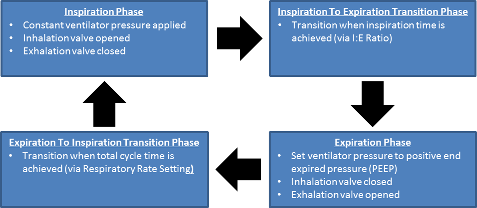 Figure 1 Flow diagram showing the ventilatory cycles as implemented in the Anesthesia Machine.
 Process Actions
Process Actions deals with modification of the anesthesia machine parameters and circuit properties due to actions (insults) being specified by the user. The insults are described in the Actions section below.
Update Resistances
The breathing circuit of the commonly used Anesthesia Machine is comprised of unidirectional valves on the inspiratory and expiratory limbs that control the flow of gases during the inspiration and expiration phases. The Anesthesia Machine incorporates the unidirectional valves using resistors and logical on/off conditions that serve as switches. These resistors are updated depending on the phase of the respiration cycle. During the inspiratory phase of the breathing cycle, the unidirectional valve on the inspiratory limb is opened to flow by employing a predefined low resistance, providing an electrical analogue to a closed circuit. At the same time, the unidirectional valve at the expiratory limb is closed to flow by employing a very high resistance, providing an electrical analogue to an open circuit. The process is reversed during the expiratory phase of the breathing cycle. In addition to the normal breathing cycles, the valve resistances are also modified to model various equipment failures such as inspiratory/expiratory valve leaks and obstructions.
Ventilator Pressure Calculation
In the use of the Anesthesia Machine, there are two basic ventilation modes for precise control of ventilation. These are the pressure controlled and volume-controlled modes. In the volume-controlled mode, the Anesthesia Machine delivers a preset tidal volume to generate ventilation. In this delivery mode, positive-pressure ventilation is delivered at a predetermined breathing frequency and tidal volume to provide predictable minute ventilation. In the pressure-controlled ventilation mode, a set plateau (control) pressure is delivered at each breathing cycle. The tidal volume delivered to the patient is an outcome of the control ventilator pressure and the lung compliance of the patient. The current version of the Anesthesia Machine employs the pressure-controlled ventilator. During each inspiratory phase, a constant control pressure that serves as a driving pressure source is applied to the ventilator. This pressure drives flow across the inspiratory limb path to supply gas to the patient. During the expiratory phase, the ventilator driver pressure drops to a much lower pressure, allowing gas to return to the ventilator. In the engine, the volume of the ventilator is adjusted based on the gas flow into the ventilator node.
Gas Inlet Flow Calculation
The gas inlet is modeled as a flow source to add substances to the system - both air and inhaled drugs. The inlet flow is set by the total flow parameter, and the volume fractions are based on gas source concentrations.
Breathing Cycle Calculation
The engine calculates the inspiratory and expiratory phase times based on a preset respiration rate and inspiration-expiration ratio parameters that are selected as inputs for the Anesthesia Machine configurations.
Process
The current implementation has no specific circuit or transport process functionality for the anesthesia machine. Anesthesia Machine processing is currently done in the Respiratory System with the combined circuit methodology. However, the substance volume fractions and volumes are updated to remove carbon dioxide in the scrubber during this step.
Postprocess
The Postprocess step moves values calculated in the Process step from the next time step calculation to the current time step calculation. The current implementation has no specific post process functionality for the anesthesia machine. All postprocessing is done in the Respiratory System with the combined circuit methodology.
Features and Capabilities
The Anesthesia Machine Circuit
The Anesthesia Machine System represents a generic mechanical ventilation system. It models a semi-closed anesthesia breathing circuit that employs a pressure-control mode of positive-pressure ventilation. The Model is designed to represent the functions of a ventilator, breathing circuit, and vaporizer of a typical Anesthesia Delivery System. To incorporate these functionalities, the Anesthesia Machine comprises seven major compartments. These compartments correspond to the three flow tubes (the Y-piece and the inspiratory and expiratory tubes), the CO2 absorber, the fresh gas inlet of the breathing circuit, the ventilator, and the mask compartments. The fresh gas inlet allows the flow of volatile anesthetic medications and fresh gas into the breathing circuit. In the model, the vaporizer functionality of anesthesia machines is incorporated by adjusting the concentration of the gas mixture delivered through the fresh gas inlet. In anesthesia machine systems, vaporizers are designed to hold only one specific volatile anesthetic medication. Accordingly, the Anesthesia Model reproduces this functionality by employing conditions that represent left and right chambers, each of which hold a specific inhaled agent. The model treats the agents in these chambers as vapor and mixes them with other gases to be delivered into the breathing circuit. Depending on the amount of oxygen and/or inhaled volatile gases selected, the Anesthesia Model adjusts the total gas mixture to the level of oxygen and/or volatile gases selected. In particular, the model deducts the volume fraction of the nitrogen gas proportional to the oxygen and/or inhaled volatile gases concentration.
In this way, the Anesthesia Machine captures the effect of the vaporizer functionality. For delivering supplemental oxygen, the model offers conditions that can be used to represent a separate wall port or an oxygen bottle as options. The model comprises two oxygen bottles that can be used one after the other, depending on the length of anesthesia delivery and oxygen depletion. In the event of endotracheal intubation, the mask compartment is replaced by the endotracheal tube compartment. These two compartments are used interchangeably. The inspiratory and expiratory flow tube compartments are regulated by unidirectional valve switches and allow gas flow into and out of the lung. The ventilator compartment supports positive-pressure ventilation for oxygen delivery and ventilation. Among the remaining compartments, the CO2 absorber canister compartment belongs to an important part of the breathing circle of the Anesthesia System that reduces the amount of inhaled CO2 in re-breathed gas. The diagram in Figure 2 presents the compartmental view of the Anesthesia Delivery System.
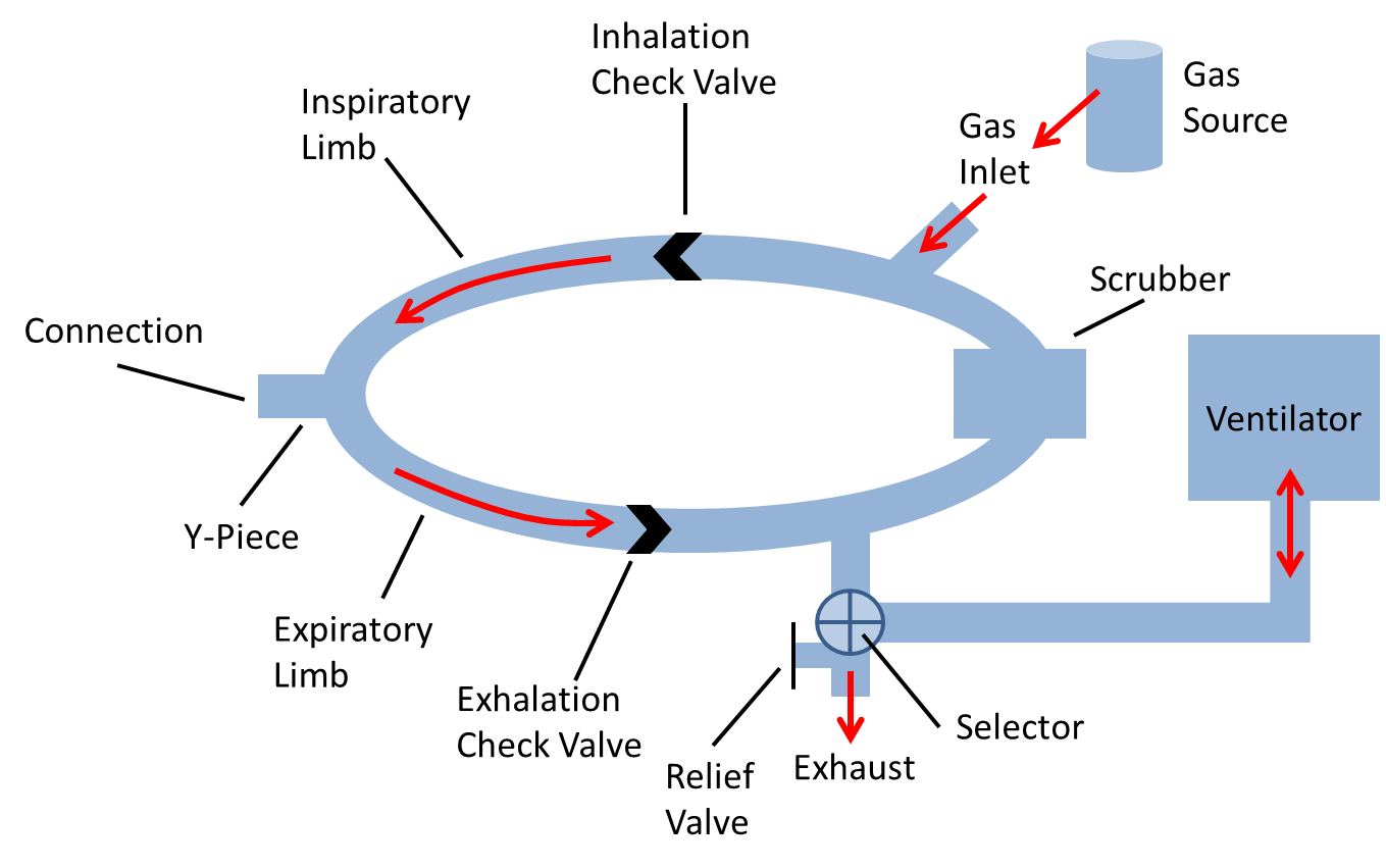 Figure 2 Compartmental view of the Anesthesia System. The Anesthesia Machine consists of seven major compartments, as shown in the breathing circuit. These are the mask/endotracheal tube compartment, the Y-piece, the inspiratory and expiratory limbs, the fresh gas inlet, the CO2 absorber, and the ventilator compartments. The mask and the endotracheal tube compartments are interchangeable. The unidirectional switches shown on the inspiratory and expiratory limbs permits unidirectional airflow in the patient's breathing cycle. The connecting lines represent the flow of gas between compartments and, the arrows show the flow direction. The red lines and the associated arrows in the figure show flow direction during the inspiratory phase. The Anesthesia Machine handles the delivery of anesthetic drug and other medical gases through approaches that allow inhaled gas delivery. The model also consists of a relief valve path that emulates the exhaust scavenging interface. The Anesthesia Machine also interacts with the Respiratory System through a circuit path that links the two systems at the airway node.
Compartments in the Anesthesia System are modeled as a network of resistors to account for the resistance to flow through each compartment. The ventilator is designed to accumulate volume on its node based on the flow across its path. When mechanical ventilation is not invoked, the model switches to spontaneous breathing via negative pressure ventilation that is driven by the respiratory muscle pressure.
The gas flowing in different Anesthesia Machine compartments is driven by pressure gradients across the resistors representing the flow resistances in the breathing circuit. The flow resistances in the breathing circuit mainly arise from regions in the circuit where there are constriction and unidirectional valves. These regions cause more significant resistance to the flow than the remainder of the breathing circle. Since practically all of the pressure drops occur across these resistors, the circuit diagram (shown below) representing the pressure gradient and the resistance to the flow appear to have a different form from the compartmental view diagram shown above. In the circuit diagram, the mask and the Y-piece are connected together as a single node, whereas a current source at the node represents a leak at the mask. The exhaust represents a leak to the atmosphere or a scavenging system to relieve breathing circuit pressure build up. Normally, the exhaust is connected to a breathing bag reservoir; however, the current version lacks such a reservoir, and the exhaust in the circuit diagram serves as a current source that facilitates appropriate pressure maintenance.
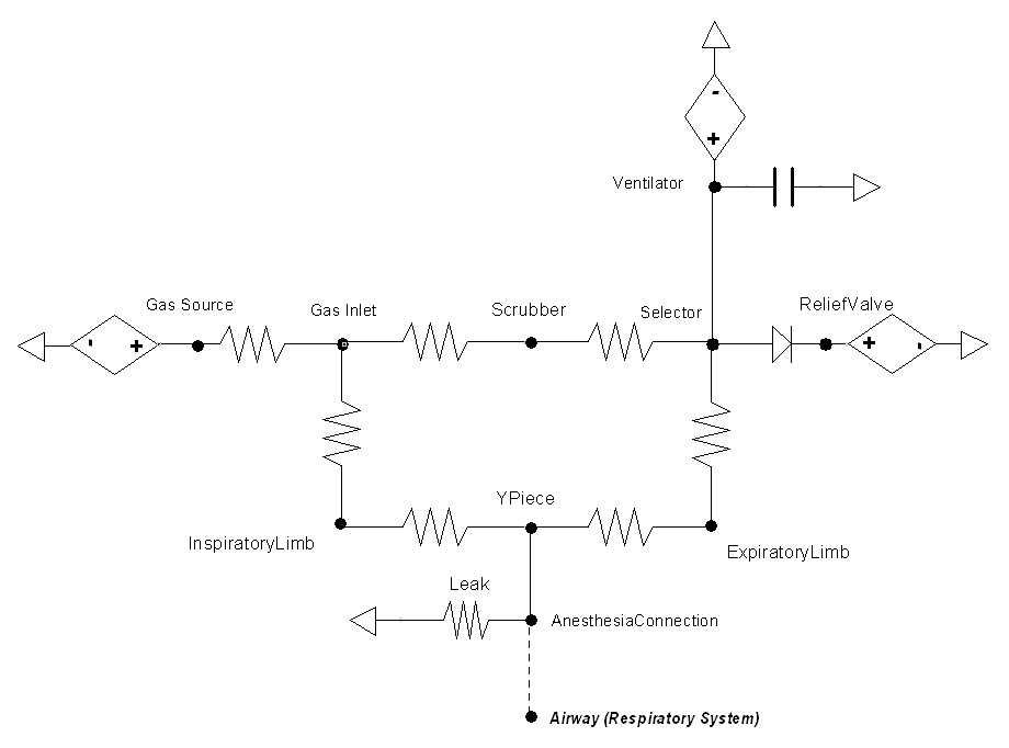 Figure 3 Circuit diagram of the Anesthesia Machine. The circuit employs the ventilator as a driver pressure source. One of the two pressure sources is selected using the switch. The fresh gas inlet serves as a current source that drives fresh gas and anesthetic drugs into the breathing circuit. When the Anesthesia Machine is turned on, the switch between the mask (represented as AnesthesiaConnection) and the mouth node of the Respiratory System becomes closed. The switch between the mask and the mouth node remains open when the Anesthesia Machine is turned off. The unidirectional valves of the Anesthesia Machine are handled by assigning very high resistance on the inspiratory or expiratory limbs depending on the breathing phase.
Connecting to the Respiratory Circuit
When an anesthesia machine is used on a patient, there is a direct connection that allows air to flow freely between both. In the same fashion, the Anesthesia Machine and Respiratory circuits in the engine are directly connected and allowed to share the same fluid. When the machine is turned on, both individually defined circuits are combined into a single circuit that is then used for calculations.
The Anesthesia Machine Settings
Anesthesia machines operate in a specific mode for positive-pressure delivery. As mentioned above, there are two modes of ventilation commonly used. The Anesthesia Machine employs a pressure-controlled ventilator for positive-pressure ventilation.
To achieve this, a set of predefined parameters are selected to control the Anesthesia Machine configuration. The Anesthesia Machine assigns the values of the ventilator pressure, respiration rate, inspiration-to-expiration ratio, relief valve pressure, and positive end expired pressure as input parameters. Additionally, the model assigns a set of parameters to control the fresh gas flow and the various gas fractions delivered to the breathing circuit. Table 1 lists the Anesthesia Machine configuration settings currently used in the engine. It should be noted that the current version of the Anesthesia Machine Model is restricted to the values listed in the table until a wide range of values are tested. Future versions will allow user-selected Anesthesia Machine setting parameters.
| Parameter | Description |
|---|---|
| General Anesthesia Machine Settings | |
| State (on/off) | Determines if the Anesthesia machine is running or not |
| VentilatorPressure | The maximum ventilator pressure applied each cycle |
| RespiratoryRate | Frequency of the ventilator |
| PositiveEndExpiratoryPressure | The minimum ventilator pressure applied each cycle |
| InspiratoryExpiratoryRatio | The relative ratio of the period of positive and negative flow in and out of the lungs |
| ReliefValvePressure | The pressure at which air will be vented out of the machine - pressure will not be able to go above this |
| Gas Inlet Settings | |
| InletFlow | The quantity of flow from the Oxygen Source |
| OxygenFraction | Sets the volume fraction of oxygen in delivered mixture |
| PrimaryGas (Nitrogen/Air) | Sets a selection for primary gas, such as air (ambient) or nitrogen |
| OxygenSource (Bottle 1/Bottle 2/Wall) | Sets the source of the gas composition to be used |
| OxygenBottleOneVolume | Sets the volume of the first oxygen Source tank |
| OxygenBottleTwoVolume | Sets the volume of the second oxygen Source tank |
| Related Settings | |
| AirwayMode (Free/Mask/Tube) | Used to add or remove the mask or tube via Actions |
| SubstanceAdministration | Substances are added to the vaporizer (i.e. gas source) by specifying a substance and chamber (left or right) |
Dependencies
The Anesthesia Machine interacts with the Respiratory System through a connection that delivers gases and anesthesia drugs into the Respiratory System (see Respiratory Methodology). The two systems are connected to each other through a path that connects the mouth node of the Respiratory System to the mask/endotracheal node (referred as AnesthesiaConnection in the circuit diagram) of the anesthesia system. During spontaneous ventilation, the mouth node of the Respiratory System is connected to the atmosphere via the Environment System. This serves as a ground node for the Respiratory System.
When the Anesthesia Machine is turned on, a network of combined circuits that include the elements from both the Respiratory and Anesthesia Systems is created. When the combined circuit is generated at runtime, the ground environment node connected to the mouth node of the Respiratory System is replaced by the AnesthesiaConnection node that represents the mask/endotracheal node, becoming one combined circuit. Apart from such interaction, the Anesthesia Delivery System is also responsive to the flow resistances of the Respiratory System. In this regard, the ventilator driver pressure serves as a positive-pressure source for the combined circuit. This allows the Anesthesia System to manage pressure-controlled ventilation. For providing air into the breathing circuit, the Anesthesia Machine is linked to the Environment System that regulates the gas concentration and atmospheric pressure. The engine Anesthesia System has system data that allows for selection of the primary gas, e.g., air, nitrogen, etc. Based on the primary gas, the delivery of supplemental oxygen and/or anesthetic gases adjusts the composition and fraction of gases derived from the Environment System (see Environment Methodology).
Assumptions and Limitations
The Anesthesia Machine is a generic model to represent the various components available in the administration of inhaled agents and mechanical ventilation. This system is intended to provide a model that can simulate the response of the body to positive-pressure ventilation, drug administration, and failures of the equipment to provide adequate gas mixtures or gas mixtures of the appropriate concentrations. The model employs a pressure-controlled, positive-pressure ventilation mode and sets a constant ventilator pressure to drive inspiration.
Currently, there are two limitations with the model. First, the model does not allow manual breathing using a bag reservoir as a pressure source. Secondly, the current version of the model is designed to deliver a set number of breaths per minute, as expected for pressure-controlled or volume-controlled ventilators. This is necessary when modeling a fully paralyzed patient. However, for anesthetic cases that don't require complete muscle paralysis, a synchronized ventilation that allows a patient's spontaneous breathing would be necessary. The current version of the anesthesia system does not allow synchronized positive-pressure ventilation with spontaneous breathing. Future efforts may be directed towards rectifying this limitation.
Actions
The Anesthesia Machine can model a variety of different equipment failures. Breathing circuit disconnection is a leading cause of critical incidents in anesthesia [320] [127] . Disconnections, which are effectively leaks, can be complete or partial. Some of these failures are modeled in the engine by changing a resistance value based on the severity. Figure 4 shows the resistance value that is set based on the insult severity and will be referenced throughout the rest of this section. We have chosen a resistance of 1000 cmH2O-s/L to be associated with a fully open switch (closed valve) and a resistance of 0.001 cmH2O-s/L to represent a fully closed switch (open valve). Intermediate resistances map logarithmically between those two extents. Several insults modify the same resistance that leads to ground (atmosphere) because the change in flow produced by the ventilator reaches the patient in the same way.
 Figure 4 This plot shows the resistance value that is set based on the leak severity modifier. The severity is mapped logarithmically in a manner that allows the highest severity to allow virtually all flow through the path and the lowest severity to allow almost no flow through the path. Obstructions use the same function with the severity reversed (i.e., 1-severity).
Connection Leaks
The following three types of leaks are all implemented the same in the Anesthesia Machine code. The mask/tube leaks and the Y-piece disconnect can be called simultaneously, and the severities will be combined.
Mask Leak
One of the most common equipment failures in the anesthetic delivery system is the mask leak. If a mask is being used on an Anesthesia Machine and is improperly secured or has damage, leaks can occur. The engine models mask leaks by varying a resistance based on the severity in the manner previously described and shown in Figure 4.
Tube Leak
Endotracheal tube cuff leaks are often caused by a structural defects in the endotracheal tube, but may also arise from improper placement or a failure to fully inflate the cuff. Large leaks can lead to inadequate ventilation. The engine models endotracheal tube leaks by varying a resistance based on severity in the manner previously described and shown in Figure 4.
Y-Piece Disconnect
The most common disconnection site is at the Y-piece [320] [127] . The engine models endotracheal tube leaks by varying a resistance based on the severity in the manner previously described and shown in Figure 4. In the case of both a tube and Y-piece leak, the severities are combined and limited to a total value of one.
Valve Leaks
Inspiratory and expiratory valves leaks are both similar to endotracheal tube cuff leaks. The valves are modeled as resistors that alternate between very high and very low resistance values to mimic a switch opening and closing every breath cycle. This prevents rebreathing of carbon dioxide during the respiration cycle. If there is a leak present, the valve closed (i.e., high resistance) value is modified based on the severity in the manner previously described and shown in Figure 4.
Valve Obstructions
Anesthesia Machine tracheal tubes can become kinked, and hoses throughout the breathing circuit are subject to occlusions by external mechanical forces that can impinge the flow [320] [127] . The engine models both inspiratory and expiratory valve obstructions similarly to leaks, by modifying the valve resistance values. If there is an obstruction present, the valve open (i.e., low resistance) value is modified based on the severity in the manner previously described and shown in Figure 4.
Ventilator Pressure Loss
Both piston and bellows ventilators can sometimes experience mechanical failures that prevent them from filling completely. This causes the driving pressure of the ventilator to be less than the target. The engine uses a ventilator failure severity to linearly reduce the pressure produced by the ventilator, i.e., the pressure source value. The pressure source can range from the full calculated value to a zero pressure. Failure in ventilator pressure may affect the amount of tidal volume delivered to the patient, which in turn reduces the amount of fresh gas delivered to the body, affecting the oxygen saturation level and other physiological parameters.
Soda Lime Failure
Re-breathing circuits direct expired gases through soda lime granules to remove CO2. To ensure that a soda lime canister (CO2 absorber) is functioning properly, it must be replaced regularly. If it is not monitored and replaced, the absorber will become less effective or completely unable to remove at CO2 from the breathing circuit. The Anesthesia Machine models soda lime failure by reducing the amount of CO2 removed. The severity linearly decreases the amount of CO2 removed.
Vaporizer Failure
Vaporizers in anesthesia machines convert volatile anesthetic medications from a liquid to a set concentration gas for delivery to a patient. Anesthesia Machine vaporizers can fail due to component problems such as leaks in seals and O-rings or electronics failures. The engine models vaporizer failures by reducing the inhaled agent volume fraction at the vaporizer flow source linearly with the severity.
Oxygen Supply Failures
Supplemental oxygen is supplied to the Anesthesia System either from the wall source or oxygen tank bottle. Many scenarios, such as a problem with the oxygen pipeline, may cause disruption of gas delivery. To identify these issues, pressures in the gas supplies are often checked. The Anesthesia System attempts to capture such equipment failures by triggering oxygen wall pressure loss and oxygen tank pressure loss conditions. When the oxygen pressure loss conditions are triggered, the model removes the supplemental oxygen delivered to the gas flow inlet by setting the oxygen inlet volume fractions to zero.
Events
Oxygen Bottle Exhausted
The Anesthesia system triggers the oxygen bottle tank exhausted event to alert the user of the depletion of each of the oxygen bottles when oxygen bottle is used as a source of supplemental oxygen.
Relief Valve Active
The Anesthesia system triggers the Relief Valve Active event to alert the user when the relief valve is closed (closed in the electric analogue sense), and a condition the alerts the user when the pressure has reached the threshold value.
Results and Conclusions
Validation - Settings
The Anesthesia Machine Settings are fully dynamic and do not have any bounds enforced. A scenario that varies these settings in several different combinations is included with the code base and produces the outputs shown in Figure 5. This scenario also tests the relief valve functionality and causes the active event to be logged when the Ventilator Pressure is set too high.
 |  |
 |  |
 | |
Validation - Actions
All equipment failures in the Anesthesia Machine system were validated quantitatively where possible and qualitatively elsewhere by comparing the engine output to expected trends and values. For each scenario, the table shows the total number of results in each category. For many investigated scenarios, the model shows good agreement with the expected trends. For the scenarios that did not match with the expected trends, improvements are planned for future engine releases.
Table 2 Cumulative validation results for Anesthesia Machine specific conditions and actions scenarios.
| Key |
|---|
| Good agreement: correct trends or <10% deviation from expected |
| Some deviation: correct trend and/or <30% deviation from expected |
| Poor agreement: incorrect trends or >30% deviation from expected |
| Scenario | Description | Good | Decent | Bad |
|---|---|---|---|---|
| EndotrachealTubeLeakVaried | Tests endotracheal tube leak incidence; Succs injected and anesthesia machine is turned on. Endotracheal tube is intubated and multiple levels (severity: 0.5, 1.0) of tube cuff leak is tested. | 30 | 0 | 0 |
| ExpiratoryValveLeakVaried | Tests multiple levels (severity: 0.5, 1.0) of expiratory valve leak event. Succs injected, anesthesia machine is turned on, and mask is placed. | 29 | 1 | 0 |
| ExpiratoryValveObstructionVaried | Tests multiple levels (severity: 0.5, 1.0) of expiratory valve obstruction event. Succs injected, anesthesia machine is turned on, and mask is placed. | 30 | 0 | 0 |
| InspiratoryValveLeakVaried | Tests multiple levels (severity: 0.5, 1.0) of inspiratory valve leak event. Succs injected, anesthesia machine is turned on, and mask is placed. | 29 | 1 | 0 |
| InspiratoryValveObstructionVaried | Tests multiple levels (severity: 0.5, 1.0) of inspiratory valve obstruction event. Succs injected, anesthesia machine is turned on, and mask is placed. | 30 | 0 | 0 |
| MaskLeakVaried | Tests multiple levels (severity: 0.5, 1.0) of mask leak event. Succs injected, anesthesia machine is turned on, and mask is placed. | 30 | 0 | 0 |
| OxygenTankPressureLoss | Tests oxygen tank pressure loss event. Succs injected, anesthesia machine with oxygen bottle tank as oxygen source is turned on, and mask is placed. Oxygen bottle tank loss event is triggered followed by a replacement with a second oxygen bottle. | 30 | 0 | 0 |
| OxygenWallPressureLoss | Tests oxygen wall pressure loss event. Succs injected, anesthesia machine turned on, and mask is placed. Oxygen wall port is used as oxygen source. Then oxygen wall pressure loss event is triggered followed by a replacement of the wall port oxygen source by oxygen bottle tank. | 25 | 0 | 0 |
| SodaLimeFailureVaried | Tests multiple severity (0.5, 1.0) soda lime CO2 scrubber failure event. Succs injected, anesthesia machine turned on, and mask is placed. | 30 | 0 | 0 |
| VaporizorFailureVaried | Tests multiple severity (0.5, 1.0) vaporizer failure event. Succs injected, anesthesia machine turned on, and mask is placed. | 12 | 0 | 0 |
| VentilatorPressureLossVaried | Tests multiple severity (0.5, 1.0) of ventilator pressure loss event. Succs injected, anesthesia machine turned on, and mask is placed. | 30 | 0 | 0 |
| YPieceDisconnectVaried | Tests multiple levels (severity: 0.5, 1.0) of Y-piece disconnection event. Succs injected, anesthesia machine turned on, and mask is placed. | 30 | 0 | 0 |
| Total | 335 | 2 | 0 |
Connection Leaks
Mask Leak, Endotracheal Tube Leak, and Y Piece Disconnect
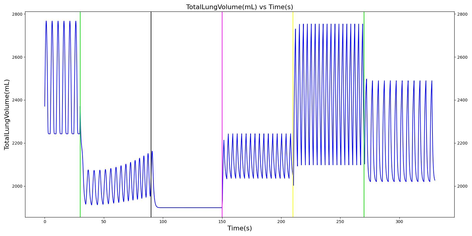
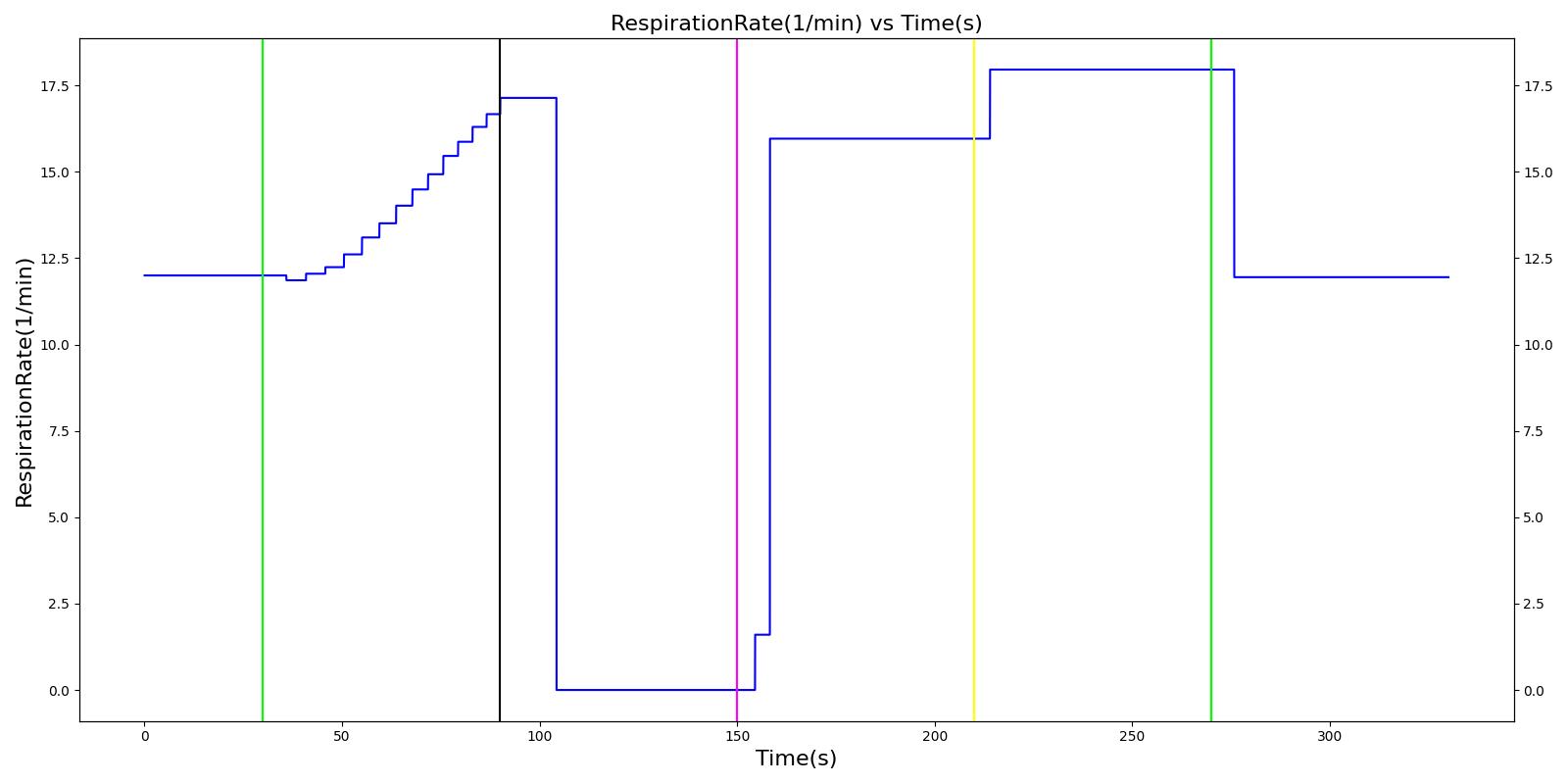
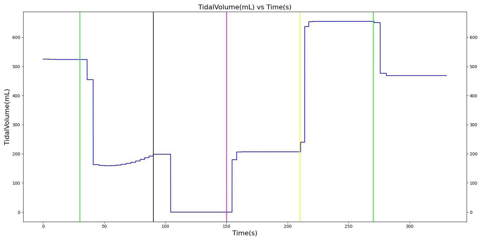
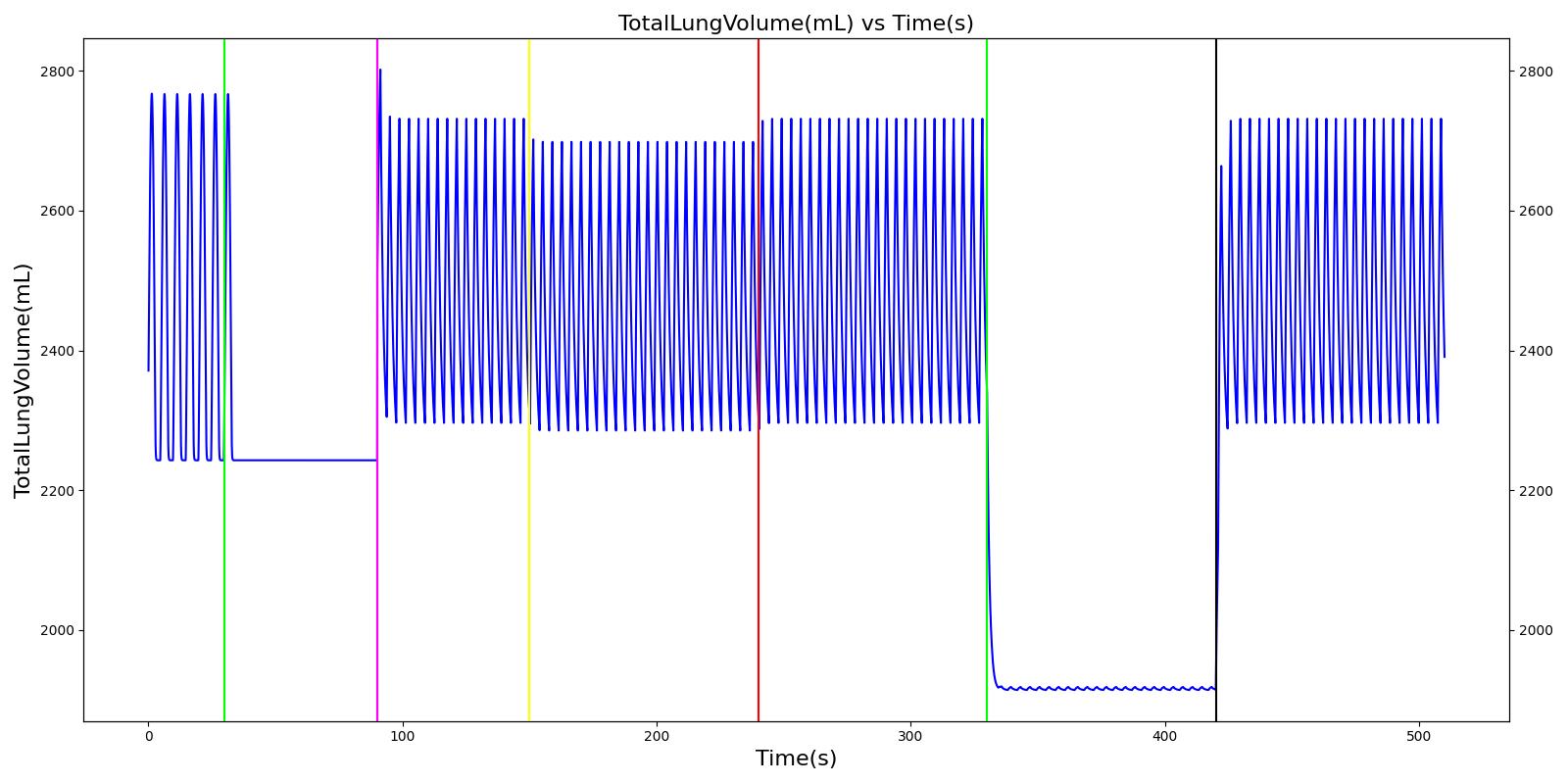
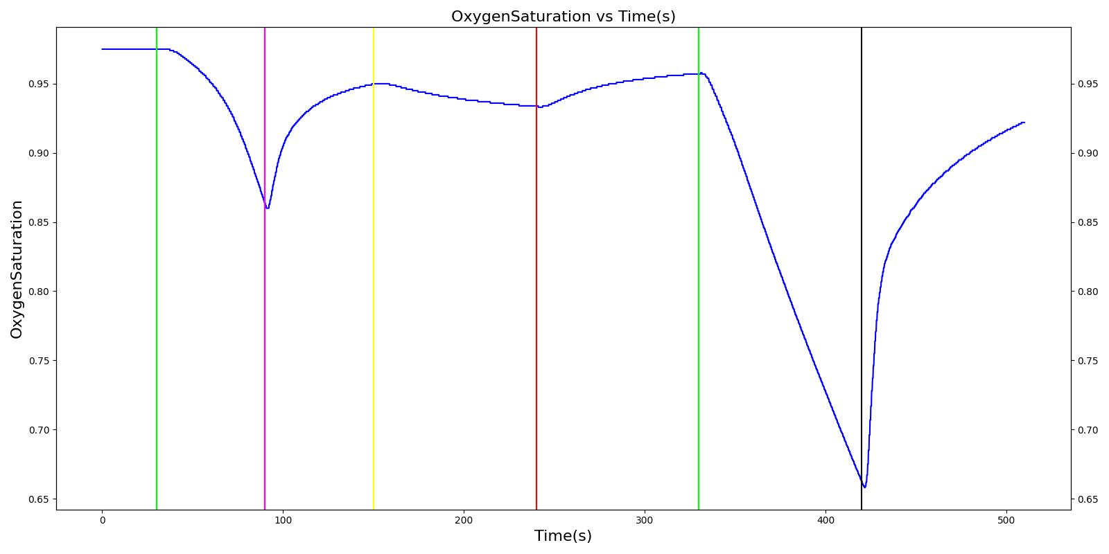
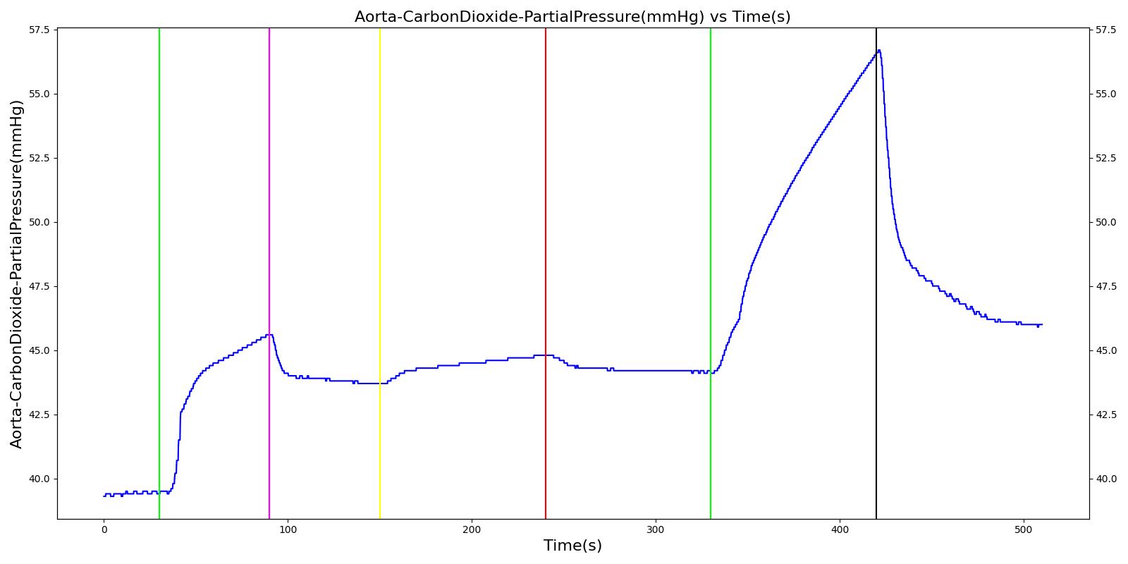
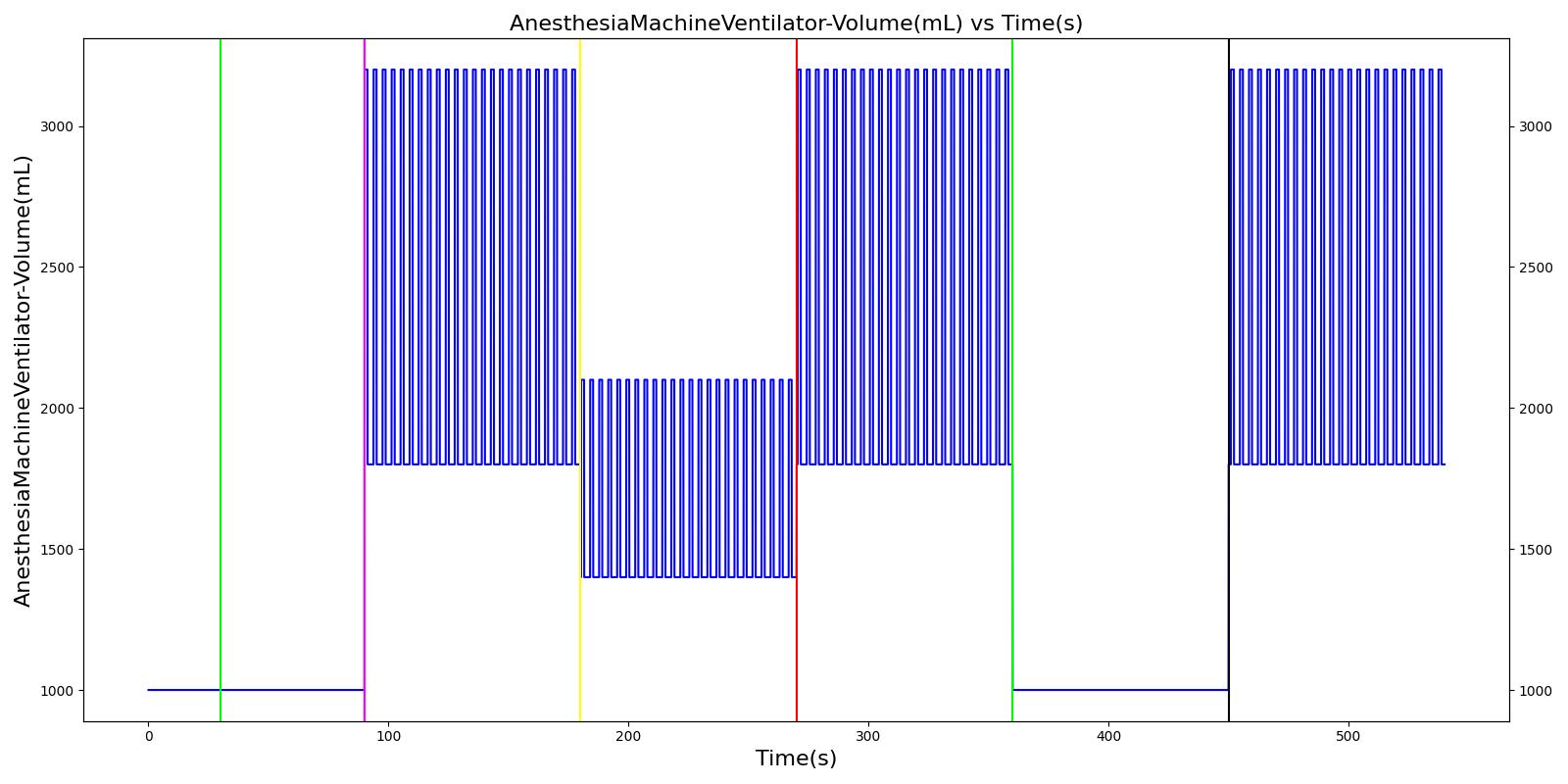
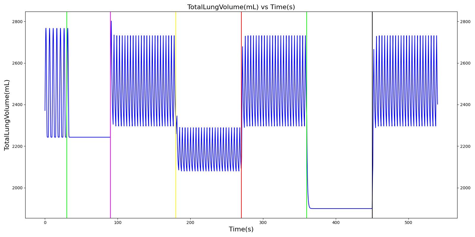
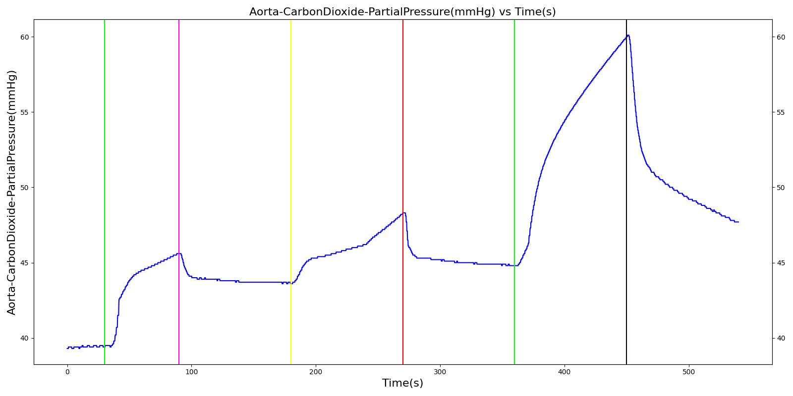
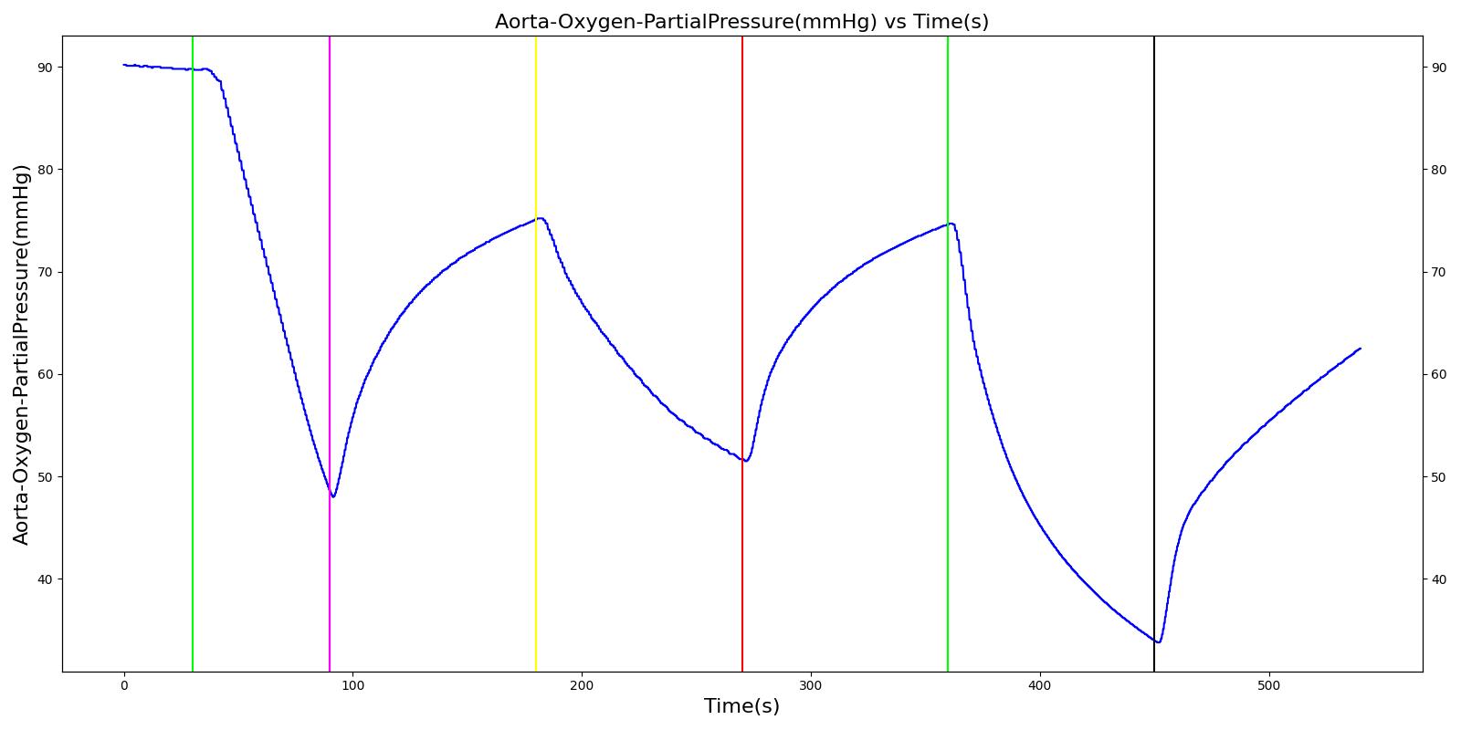
The mask leak, endotracheal tube leak, and Y-piece disconnect scenarios use the same severities at the same times. Since they share a methodology in implementation by modifying a leak reistor, they produce the same results. Each scenario begins by administering a neuromuscular blocker to cause a cessation of normal respiration. Mechanical ventilation then begins using a mask to supply the gas. The severity of the mask leak / endotracheal tube leak / Y-piece disconnect was varied. The oxygen supplied to the patient is expected to decrease with a leak, which in turn causes the oxygen saturation to drop and the carbon dioxide in the bloodstream to increase. This response is more pronounced with increasing severity.
 |  |
 |  |
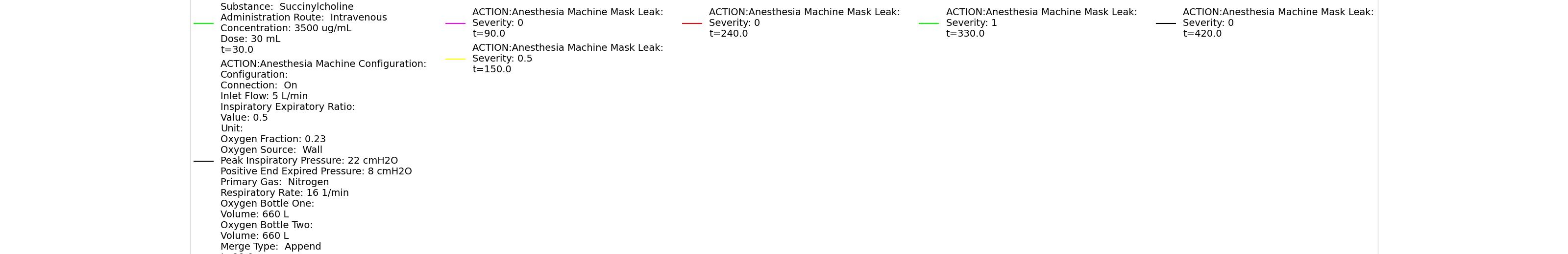 | |
Table 3 Validation matrix for physiological responses due to varying severities of leaks. MaskLeakVaried, EndotrachealTubeLeakVaried, and YPieceDisconnectVaried all give the same results.
| Segment | Notes | Action Occurrence Time (s) | Sampled Scenario Time (s) | Respiration Rate (breaths/min) | Oxygen Saturation | Tidal Volume (mL) | Aorta Oxygen Partial Pressure (mmHg) | Aorta Carbon Dioxide Partial Pressure (mmHg) |
|---|---|---|---|---|---|---|---|---|
| Administer succinylcholine. | Neuromuscular blocker agent is injected and patient stops breathing. | 30 | 90 | Goes to Zero [127] Goes to Zero [269] | Begins to drop according to desaturation curve | Goes to Zero [127] | Begins to drop w/o respiration | Begins to increase w/o respiration |
| Turn on Anesthesia Machine with leak severity of 0.0. | Place mask / insert tube. Zero severity has no effect. | 90 | 150 | 16 from machine setting | Begins to increase with return of respiration | Patient Normal Volume | Begins to increase with respiration | Begins to decrease with respiration |
| Turn on leak with severity 0.5. | Leak not severe enough to noticeably drop O2 Sat. Causes pressures below FRC, leading to higher TV. | 150 | 240 | No Change | Begins to drop according to desaturation curve | Drop in tidal volume [98] | Begins to drop w/o full tidal volume | Begins to increase w/o full tidal volume |
| Remove the leak. | 240 | 330 | No Change | Begins to increase with return of respiration | Patient Normal Volume | Begins to increase with respiration | Begins to decrease with respiration | |
| Turn on leak again with severity 1.0. | Total lung volume goes to approx. zero - RR is based on waveform, so still registers. | 330 | 420 | Goes to Zero [98] | Begins to drop according to desaturation curve | Goes to Zero [98] | Begins to drop w/o respiration | Begins to increase w/o respiration |
| Remove the leak. | 420 | 510 | 16 from machine setting | Begins to increase with return of full tidal volume | Patient Normal Volume | Begins to increase with full tidal volume | Begins to decrease with full tidal volume |
Valve Leaks
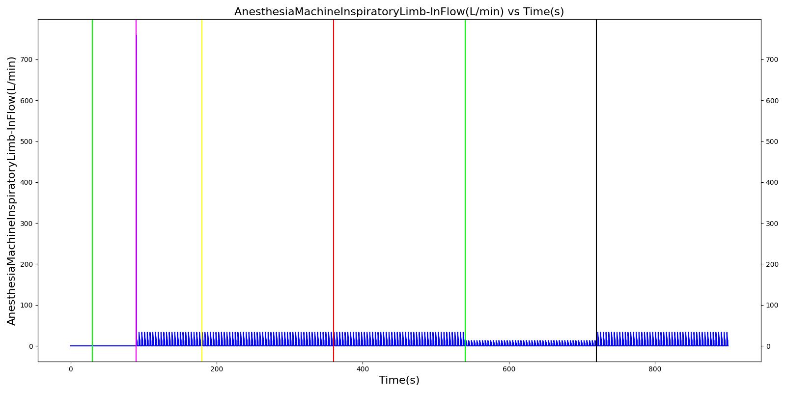
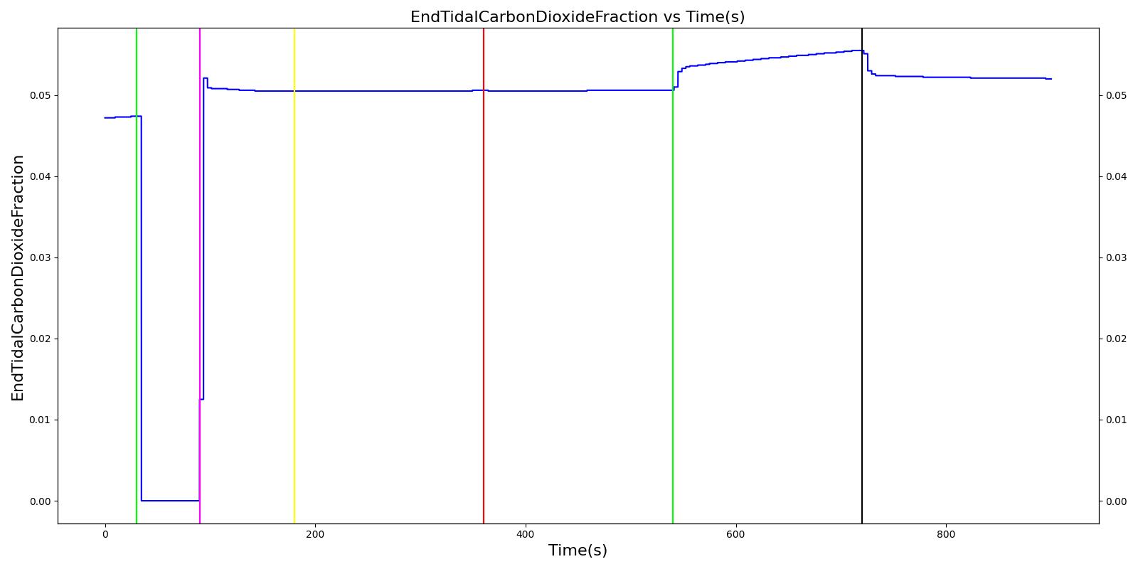
The inspiratory and expiratory valve leak scenarios begin by administering a neuromuscular blocker to cause a cessation of normal respiration. Mechanical ventilation then begins using a mask to supply the gas. The severity of the leak was varied.
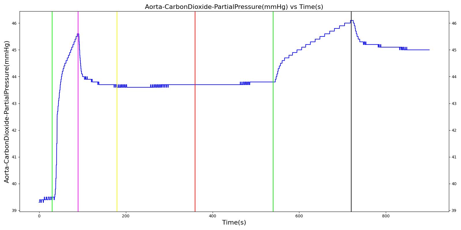
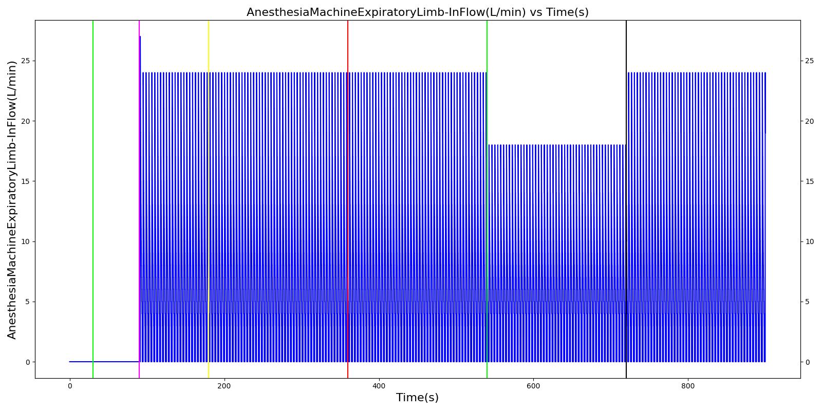
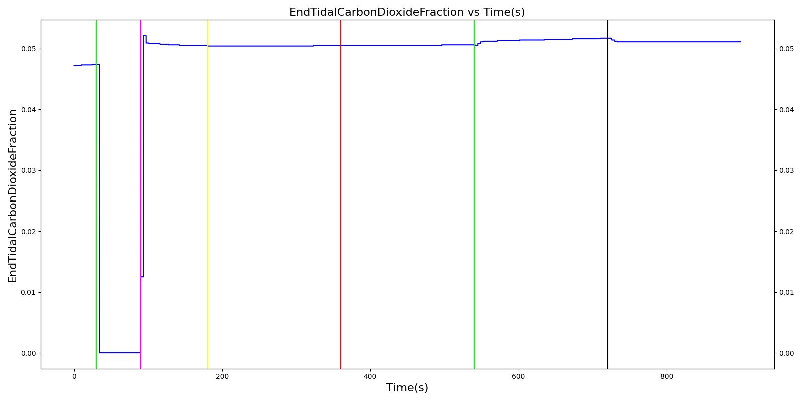
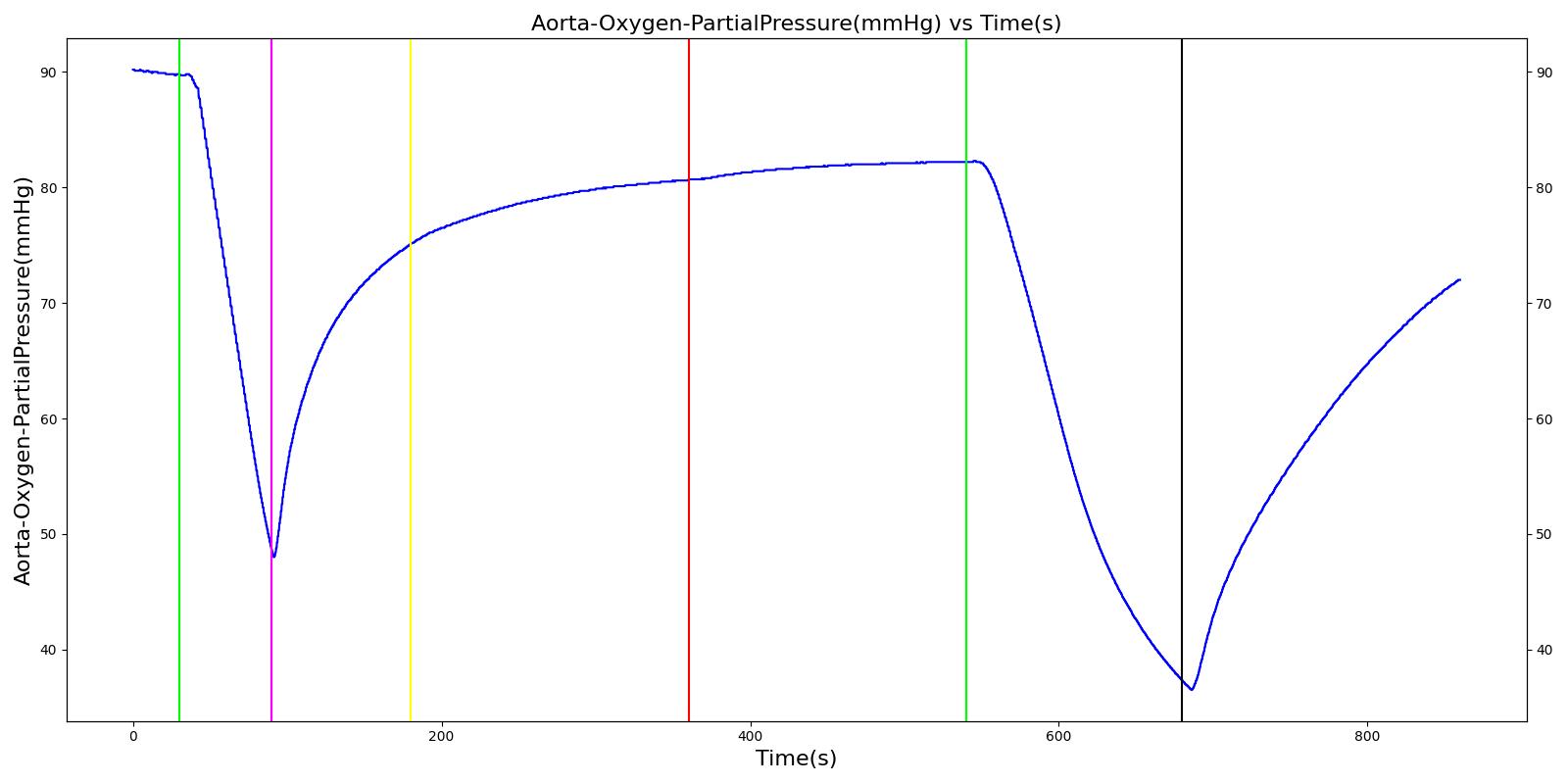
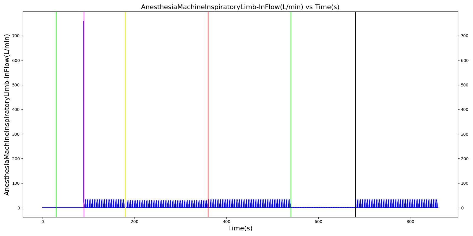
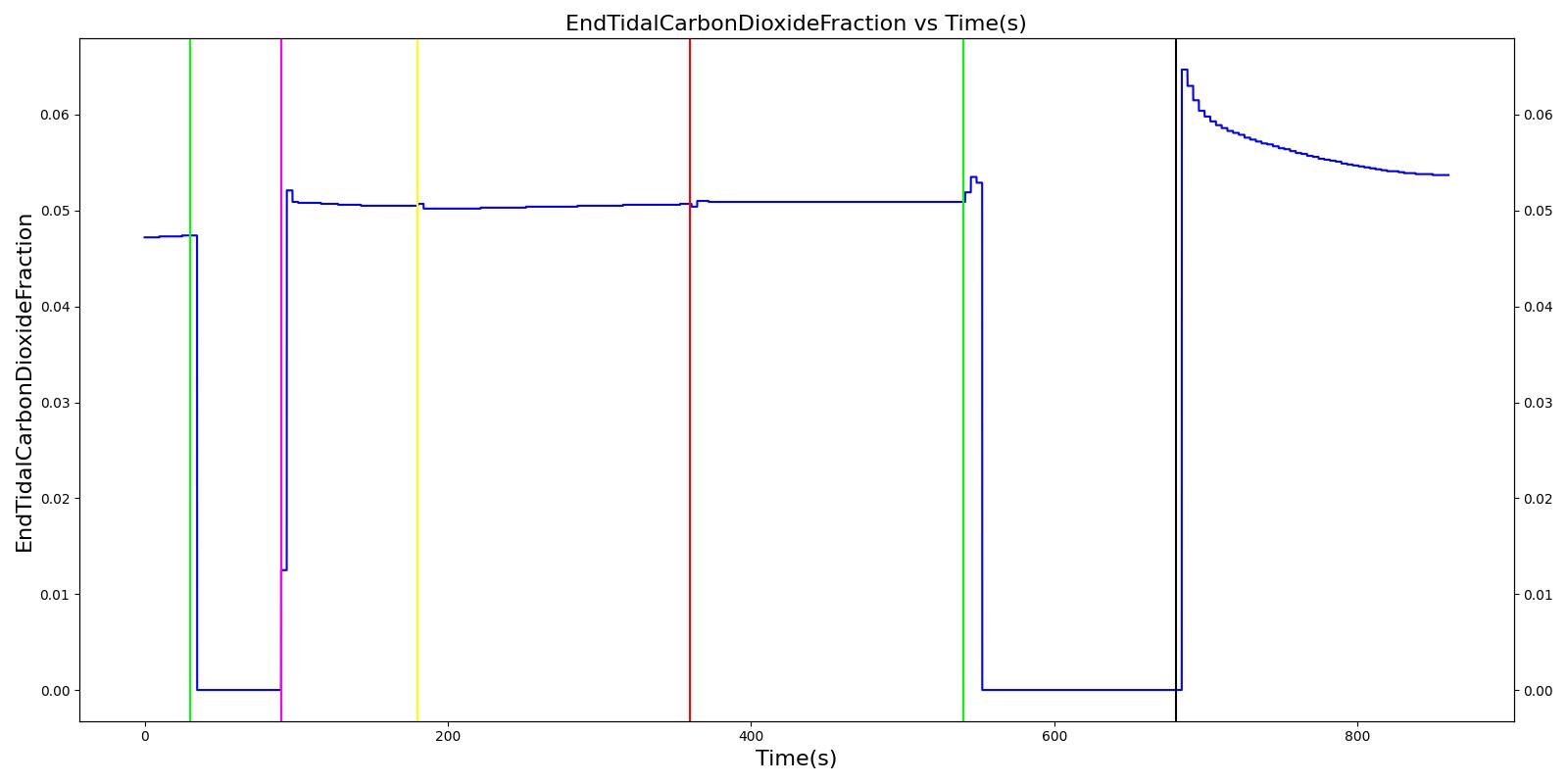
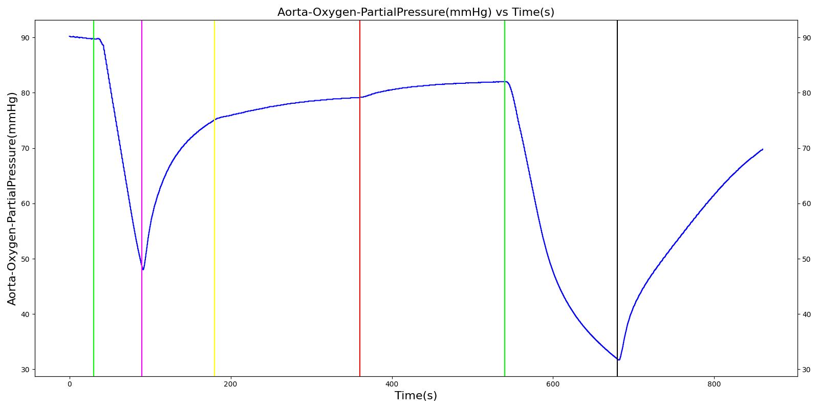
Expiratory Valve Leak
 |  |
 |  |
 | |
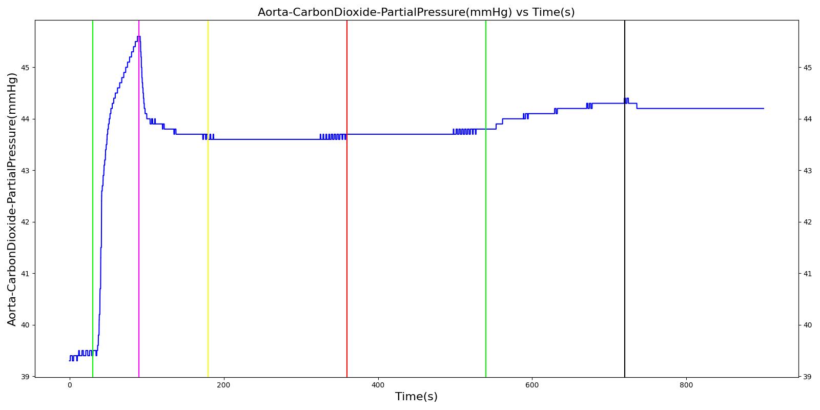
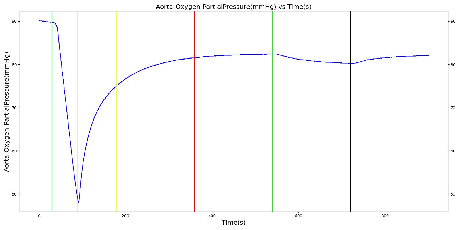
Table 4 Validation matrix for physiological responses due to varying severities of an expiratory valve leak.
| Segment | Notes | Action Occurrence Time (s) | Sampled Scenario Time (s) | Respiration Rate (breaths/min) | Oxygen Saturation | Tidal Volume (mL) | Aorta Oxygen Partial Pressure (mmHg) | Aorta Carbon Dioxide Partial Pressure (mmHg) |
|---|---|---|---|---|---|---|---|---|
| Administer succinylcholine. | Neuromuscular blocker agent is injected and patient stops breathing. | 30 | 90 | Goes to Zero [127] Goes to Zero [269] | Begins to drop according to desaturation curve | Goes to Zero [127] | Begins to drop w/o respiration | Begins to increase w/o respiration |
| Turn on Anesthesia Machine with expiratory valve leak severity of 0.0. | Place mask. Zero severity has no effect. | 90 | 180 | 16 from machine setting | Begins to increase with return of respiration | Patient Normal Volume | Begins to increase with respiration | Begins to decrease with respiration |
| Turn on expiratory valve leak with severity 0.5. | 180 | 360 | No Change [127] | No Change [127] | No Change [127] | No Change [127] | Increases leading to hypercapnia if untreated [127] | |
| Turn off expiratory valve leak. | 360 | 540 | No Change | No Change | No Change | No Change | Begins to decrease slowly return of functionality | |
| Turn on expiratory valve leak with severity 1.0. | Aorta CO2 not likely to increase all the way to hypercapnia. | 540 | 720 | No Change [127] | No Change [127] | No Change [127] | No Change [127] | Increases leading to hypercapnia if untreated [127] |
| Turn off expiratory valve leak. | 720 | 900 | No Change | No Change | No Change | No Change | Begins to decrease slowly return of functionality |
Inspiratory Valve Leak
 |  |
 |  |
 | |
Table 5 Validation matrix for physiological responses due to varying severities of an inspiratory valve leak.
| Segment | Notes | Action Occurrence Time (s) | Sampled Scenario Time (s) | Respiration Rate (breaths/min) | Oxygen Saturation | Tidal Volume (mL) | Aorta Oxygen Partial Pressure (mmHg) | Aorta Carbon Dioxide Partial Pressure (mmHg) |
|---|---|---|---|---|---|---|---|---|
| Administer succinylcholine. | Neuromuscular blocker agent is injected and patient stops breathing. | 30 | 90 | Goes to Zero [127] Goes to Zero [269] | Begins to drop according to desaturation curve | Goes to Zero [127] | Begins to drop w/o respiration | Begins to increase w/o respiration |
| Turn on Anesthesia Machine with inspiratory valve leak severity of 0.0. | Place mask. Zero severity has no effect. | 90 | 180 | 16 from machine setting | Begins to increase with return of respiration | Patient Normal Volume | Begins to increase with respiration | Begins to decrease with respiration |
| Turn on inspiratory valve leak with severity 0.5. | 180 | 360 | No Change [127] | No Change [127] | No Change [127] | No Change [127] | Increases leading to hypercapnia if untreated [127] | |
| Turn off expiratory valve obstruction. | 360 | 540 | No Change | No Change | No Change | No Change | Begins to decrease slowly return of functionality | |
| Turn on inspiratory valve leak with severity 1.0. | 540 | 720 | No Change [127] | No Change [127] | No Change [127] | No Change [127] | Increases leading to hypercapnia if untreated [127] | |
| Turn off expiratory valve obstruction. | 720 | 900 | No Change | No Change | No Change | No Change | Begins to decrease slowly return of functionality |
Valve Obstructions
The inspiratory and expiratory valve obstruction scenarios begin by administering a neuromuscular blocker to cause a cessation of normal respiration. Mechanical ventilation then begins using a mask to supply the gas. The severity of the obstruction was varied. A full obstruction has the potential to cause a complete cessation of respiration or tidal volume due to flow obstruction. Since the neuromuscular blocker freezes the patient's spontaneous breathing, the full obstruction of the valves limits the flow of air that serves as positive-pressure ventilation to inflate the lungs.
Expiratory Valve Obstruction
 |  |
 |  |
 | |
Table 6 Validation matrix for physiological responses due to varying severities of an expiratory valve obstruction.
| Segment | Notes | Action Occurrence Time (s) | Sampled Scenario Time (s) | Respiration Rate (breaths/min) | Oxygen Saturation | Tidal Volume (mL) | Aorta Oxygen Partial Pressure (mmHg) | Aorta Carbon Dioxide Partial Pressure (mmHg) |
|---|---|---|---|---|---|---|---|---|
| Administer succinylcholine. | Neuromuscular blocker agent is injected and patient stops breathing. | 30 | 90 | Goes to Zero [127] Goes to Zero [269] | Begins to drop according to desaturation curve | Goes to Zero [127] | Begins to drop w/o respiration | Begins to increase w/o respiration |
| Turn on Anesthesia Machine with expiratory valve obstruction severity of 0.0. | Place mask. Zero severity has no effect. | 90 | 180 | 16 from machine setting | Begins to increase with return of respiration | Patient Normal Volume | Begins to increase with respiration | Begins to decrease with respiration |
| Turn on expiratory valve obstruction with severity 0.5. | Leak not severe enough to noticeably increase Aorta CO2. | 180 | 360 | No Change [127] | No Change [127] | No Change [127] | No Change [127] | Increases leading to hypercapnia if untreated [127] |
| Turn off expiratory valve obstruction. | 360 | 540 | No Change | Begins to increase with return of respiration | No Change | Begins to increase with respiration | Begins to decrease slowly return of functionality | |
| Turn on expiratory valve obstruction with severity 1.0. | Total lung volume goes to approx. zero - RR is based on waveform, so still registers. | 540 | 720 | Goes to zero [319] | Begins to drop according to desaturation curve | Goes to zero [319] | Begins to drop w/o respiration | Increases leading to hypercapnia if untreated [127] |
| Turn off expiratory valve obstruction. | 720 | 900 | 16 from machine setting | Begins to increase with return of full tidal volume | No Change | Begins to increase with respiration | Begins to decrease slowly return of functionality |
Inspiratory Valve Obstruction
 |  |
 |  |
 | |
Table 7 Validation matrix for physiological responses due to varying severities of an inspiratory valve obstruction.
| Segment | Notes | Action Occurrence Time (s) | Sampled Scenario Time (s) | Respiration Rate (breaths/min) | Oxygen Saturation | Tidal Volume (mL) | Aorta Oxygen Partial Pressure (mmHg) | Aorta Carbon Dioxide Partial Pressure (mmHg) |
|---|---|---|---|---|---|---|---|---|
| Administer succinylcholine. | Neuromuscular blocker agent is injected and patient stops breathing. | 30 | 90 | Goes to Zero [127] Goes to Zero [269] | Begins to drop according to desaturation curve | Goes to Zero [127] | Begins to drop w/o respiration | Begins to increase w/o respiration |
| Turn on Anesthesia Machine with inspiratory valve obstruction severity of 0.0. | Place mask. Zero severity has no effect. | 90 | 180 | 16 from machine setting | Begins to increase with return of respiration | Patient Normal Volume | Begins to increase with respiration | Begins to decrease with respiration |
| Turn on inspiratory valve obstruction with severity 0.5. | 180 | 360 | No Change [127] | No Change [127] | Reduced tidal volume (minor)[319] | Begins to decrease without full tidal volume (very minor if at all) [319] | Increases leading to hypercapnia if untreated [127] | |
| Turn off inspiratory valve obstruction. | 360 | 540 | No Change | No Change | Return to patient normal volume with obstruction | Begins to increase with full tidal volume | Begins to decrease slowly return of functionality | |
| Turn on inspiratory valve obstruction with severity 1.0. | Total lung volume goes to approx. zero - RR is based on waveform, so still registers. | 540 | 720 | Goes to zero [319] | Begins to drop according to desaturation curve | system is obstruction reducing tidal volume [319] | Begins to decrease without full tidal volume [319] | Increases leading to hypercapnia if untreated [127] |
| Turn off inspiratory valve obstruction. | 720 | 900 | No Change | No Change | Return to patient normal volume with obstruction | Begins to increase with full tidal volume | Begins to decrease slowly return of functionality |
Ventilator Pressure Loss
The ventilator failure scenario begins by administering a neuromuscular blocker to cause a cessation of normal respiration. Mechanical ventilation then begins using a mask to supply the gas. The severity of the failure was varied. At the full failure, a cessation of respiration was expected.
 |  |
 |  |
 | |
Table 8 Validation matrix for physiological responses due to varying severities of a ventilator pressure loss.
| Segment | Notes | Action Occurance Time (s) | Sampled Scenario Time (s) | Respiration Rate (breaths/min) | Oxygen Saturation | Tidal Volume (mL) | Aorta Oxygen Partial Pressure (mmHg) | Aorta Carbon Dioxide Partial Pressure (mmHg) |
|---|---|---|---|---|---|---|---|---|
| Administer succinycholine. | Neuromuscular blocker agent is injected and patient stops breathing. | 30 | 90 | Goes to Zero [127] Goes to Zero [269] | Begins to drop according to desaturation curve | Goes to Zero [127] | Begins to drop w/o respiration | Begins to increase w/o respiration |
| Turn on Anesthesia Machine with ventilator pressure loss severity 0.0. | Place mask. Zero severity has no effect. | 90 | 180 | 16 from machine setting | Begins to increase with return of respiration | Patient Normal Volume | Begins to increase with respiration | Begins to decrease with respiration |
| Turn on ventilator pressure loss with severity 0.5. | 180 | 270 | May drop or remain at 16 depending on pressure supplied by ventilator [127] | Begins to drop according to desaturation curve [127] | Drops without full ventilator pressure [127] | Begins to decrease with lack of full tidal volume [127] | Begins to increase with lack of full tidal volume[127] | |
| Turn off Ventilator pressure loss. | 270 | 360 | 16 from machine setting | Begins to increase with return of respiration machine function [127] | Patient Normal Volume | Begins to increase with a return of ventilator function [127] | Begins to decrease with a return of ventilator function [127] | |
| Turn on ventilator pressure loss with severity 1.0. | 360 | 450 | Drops with lack of ventilator pressure [127] | Begins to drop according to desaturation curve [127] | Goes to zero with a lack of ventilator pressure [127] | Begins to decrease with lack of oxygen [127] | Begins to increase with lack of ventilator function [127] | |
| Turn off Ventilator pressure loss. | 450 | 540 | 16 from machine setting | Begins to increase with return of respiration machine function [127] | Patient Normal Volume | Begins to increase with a return of ventilator function [127] | Begins to decrease with a return of ventilator function [127] |
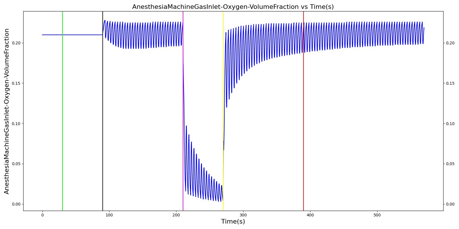
Soda Lime Failure
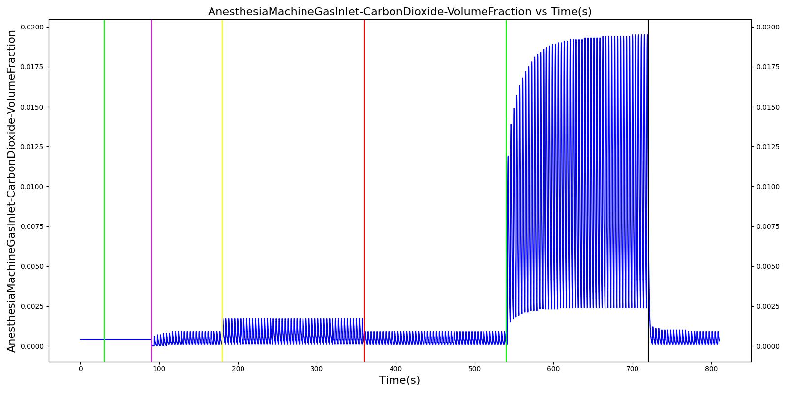
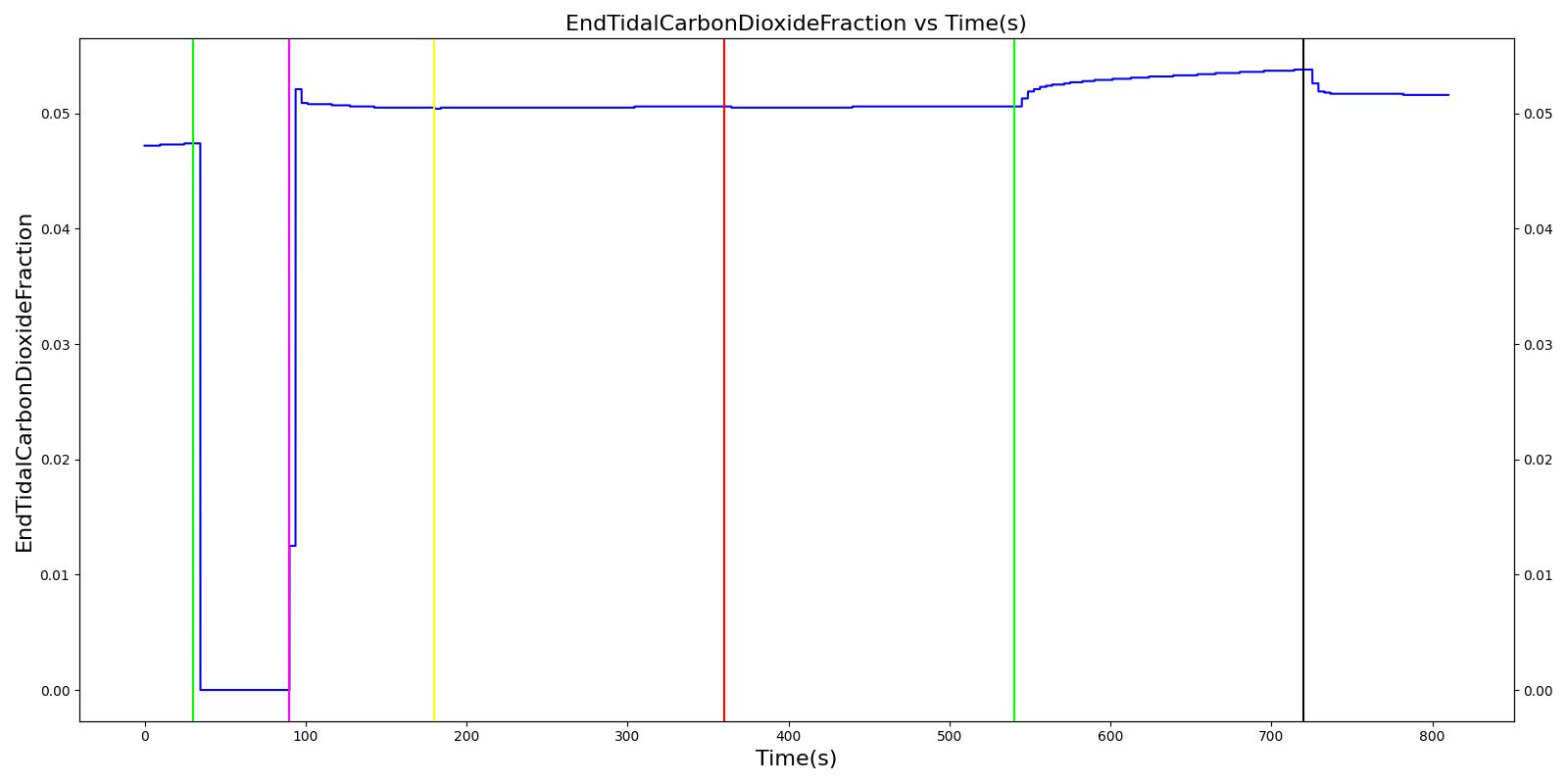
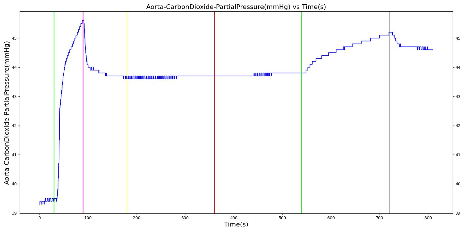
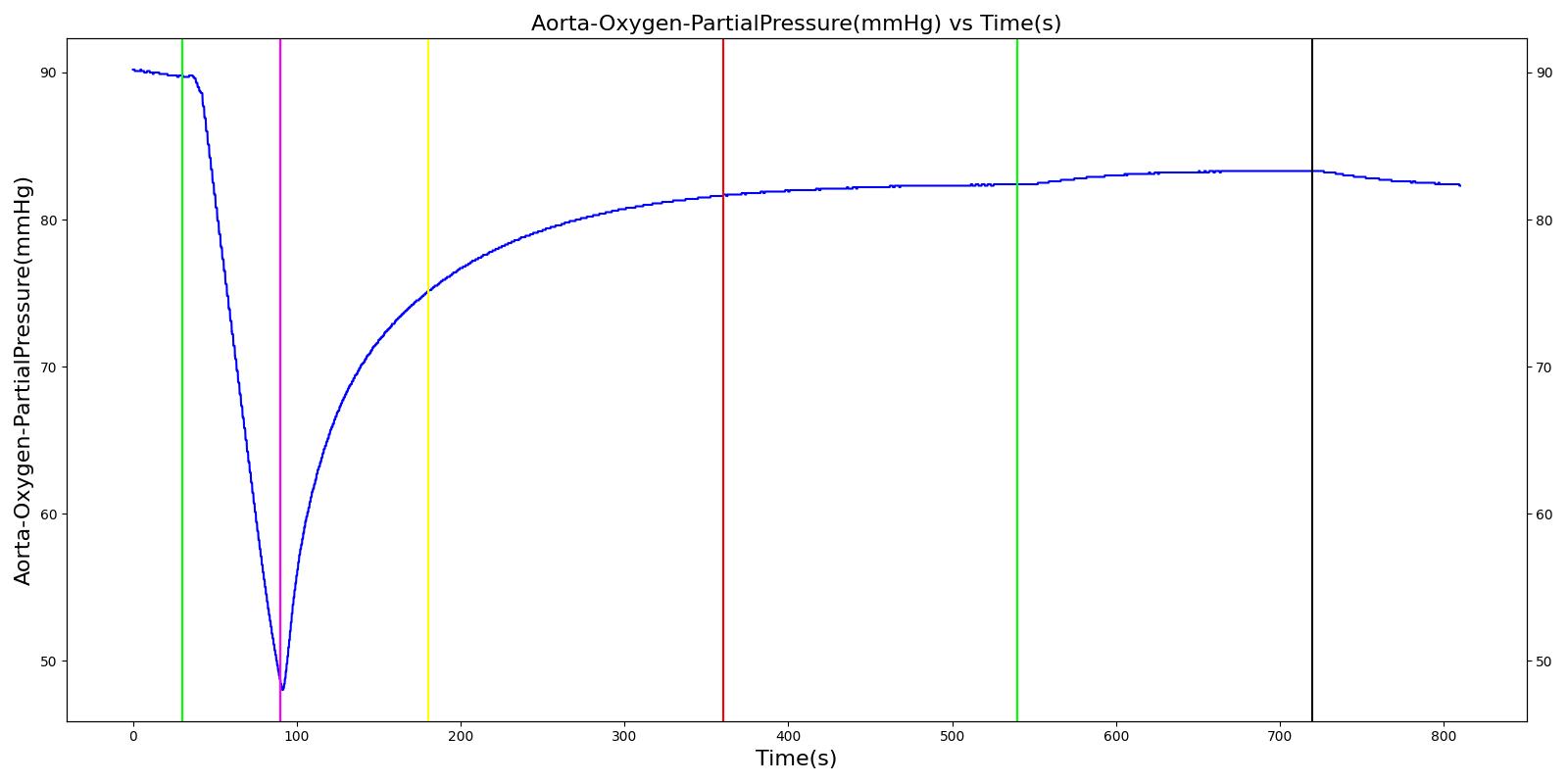
The soda lime failure scenario begins by administering a neuromuscular blocker to cause a cessation of normal respiration. Mechanical ventilation then begins using a mask to supply the gas. The severity of the failure was varied. As expected, respiration rate, tidal volume, and oxygen levels remain stable. Carbon dioxide in the blood increases.
 |  |
 |  |
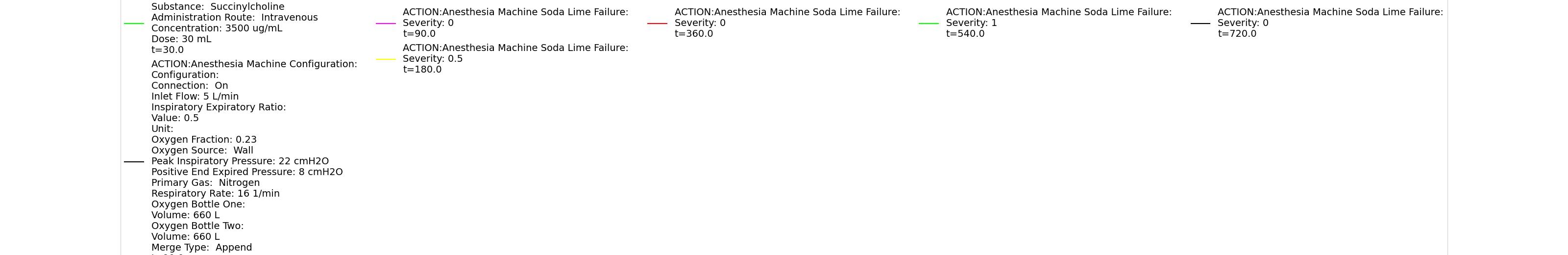 | |
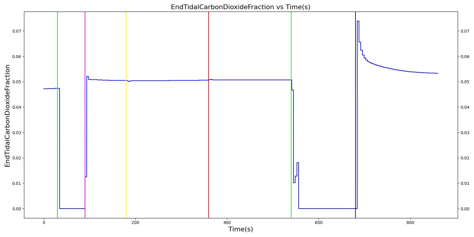
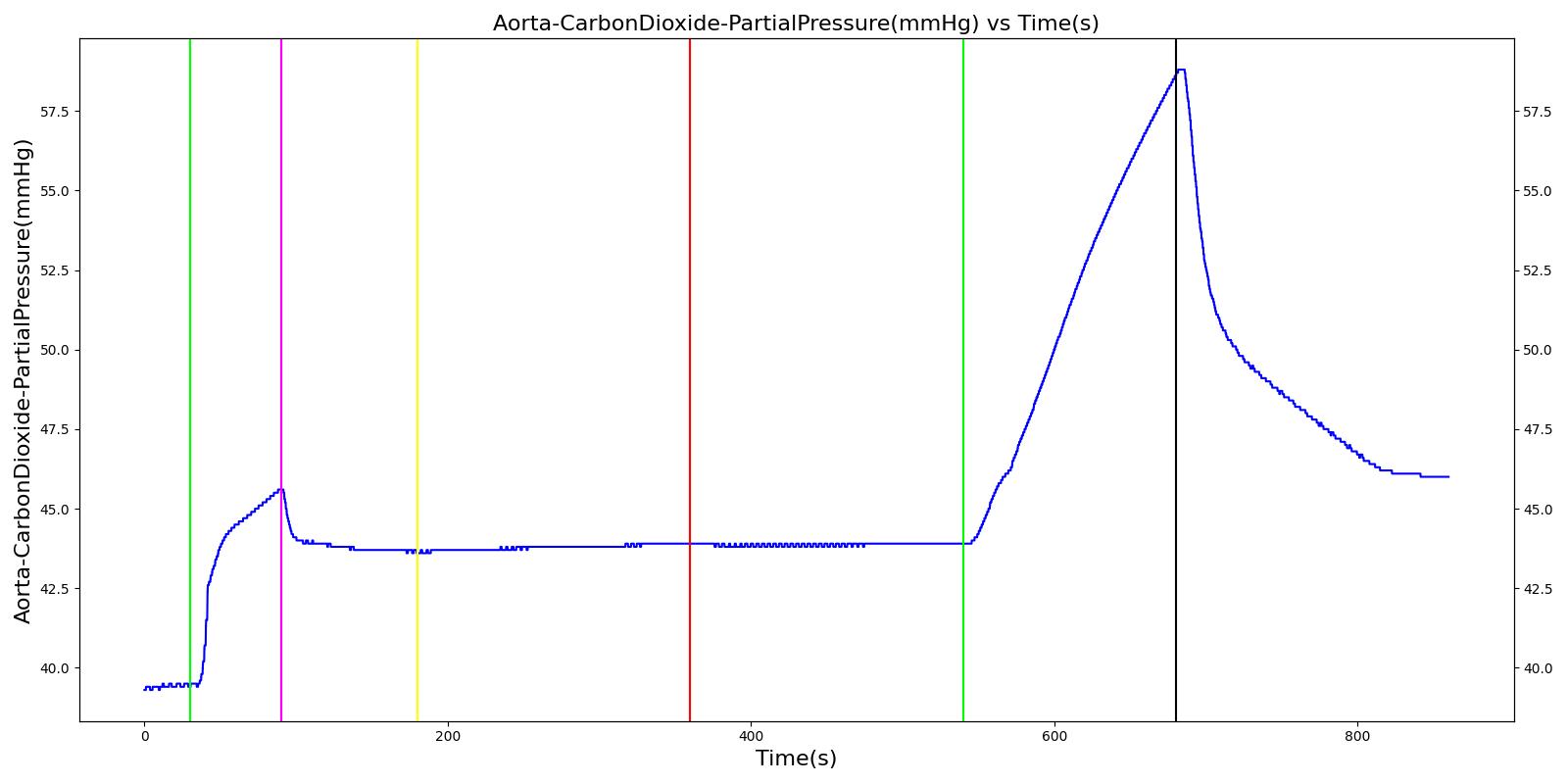
Table 9 Validation matrix for physiological responses due to varying severities of a soda lime failure.
| Segment | Notes | Action Occurrence Time (s) | Sampled Scenario Time (s) | Respiration Rate (breaths/min) | Oxygen Saturation | Tidal Volume (mL) | Aorta Oxygen Partial Pressure (mmHg) | Aorta Carbon Dioxide Partial Pressure (mmHg) |
|---|---|---|---|---|---|---|---|---|
| Administer succinylcholine. | Neuromuscular blocker agent is injected and patient stops breathing. | 30 | 90 | Goes to Zero [127] Goes to Zero [269] | Begins to drop according to desaturation curve | Goes to Zero [127] | Begins to drop w/o respiration | Begins to increase w/o respiration |
| Turn on Anesthesia Machine with soda lime failure severity 0.0. | Place mask. Zero severity has no effect. | 90 | 180 | 16 from machine setting | Begins to increase with return of respiration | Patient Normal Volume | Begins to increase with respiration | Begins to decrease with respiration |
| Turn on soda lime failure with severity 0.5. | CO2 not scrubbed as effectively. | 180 | 360 | No Change | No Change | Patient Normal Volume | No Change | Begins to increase w/ failure to absorb CO2 [319] |
| Turn off soda lime failure. | 360 | 540 | No Change | No Change | Patient Normal Volume | No Change | Begins to decrease with functional equipment [319] | |
| Turn on soda lime failure with severity 1.0. | CO2 not scrubbed at all. | 540 | 720 | No Change | No Change | Patient Normal Volume | No Change | Begins to increase w/ failure to absorb CO2 [319] |
| Turn off soda lime failure. | 720 | 810 | No Change | No Change | Patient Normal Volume | No Change | Begins to decrease with functional equipment [319] |
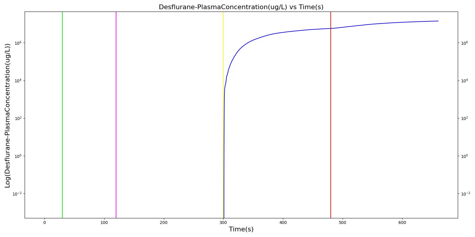
Vaporizer Failure
The vaporizer failure scenario begins by administering supplemental oxygen via a mask to the patient. As previously noted, this is a limitation of the system. Mechanical ventilation supplies gas at a prescribed respiration rate, regardless of whether the patient is conscious and breathing naturally. The Anesthesia Machine is then turned on with an inhaled agent, desflurane, being supplied. The severity of the failure was varied. At a severity of one, the vaporizer supplied no desflurane to the patient, and no changes were observed. This was the expected outcome. The drug amount increases in the system and drug effects are observed for all other severity levels.
 |
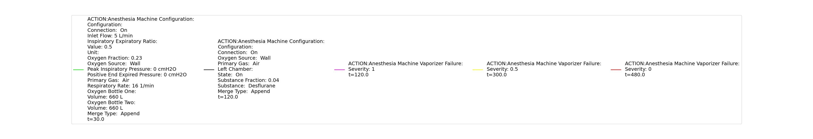 |
Table 10 Validation matrix for physiological responses due to varying severities of a vaporizer failure.
| Segment | Notes | Action Occurance Time (s) | Sampled Scenario Time (s) | Respiration Rate (breaths/min) | Tidal Volume (mL) | Drug Plasma Concentration (ug/mL) |
|---|---|---|---|---|---|---|
| Connect Anesthesia Machine. | Place mask. | 30 | 120 | No Significant Change | No Significant Change | Zero |
| Adminster drug via vaporizer. Turn on vaporizer failure of severity 1.0. | Full vaporizer failure - no drug in body. | 120 | 300 | No Change | No Change | Zero |
| Decrease vaporizer failure severity to 0.5. | 300 | 480 | Moderate Increase [127] | Moderate Increase [127] | Increase | |
| Turn off vaporizer failure. | 480 | 660 | Continued drug response [127] | Continued drug response [127] | Increase at faster rate |
Oxygen Supply Failures
Oxygen Wall Pressure Loss
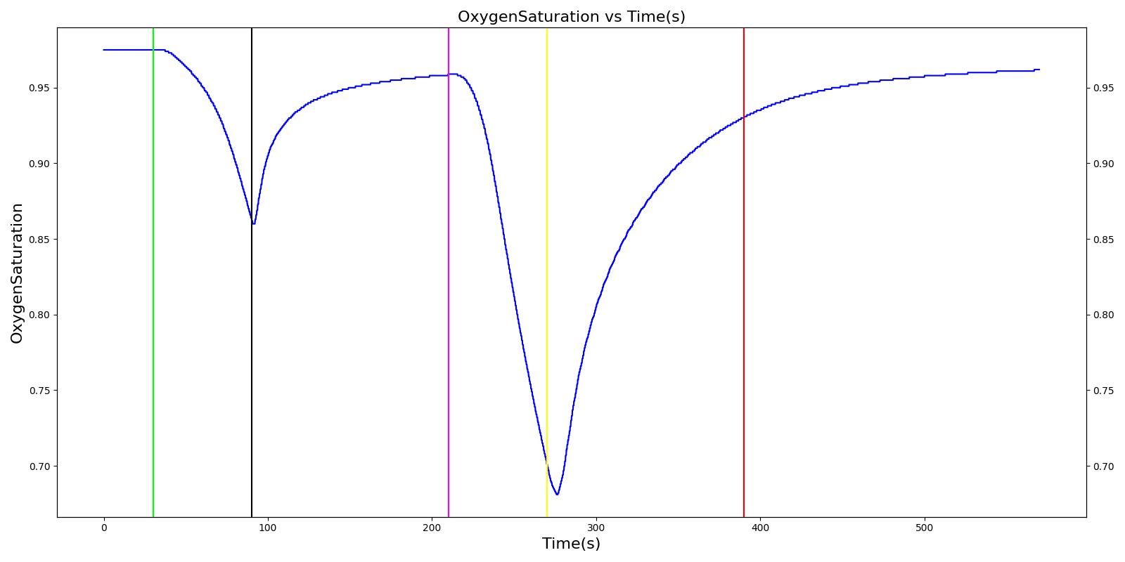
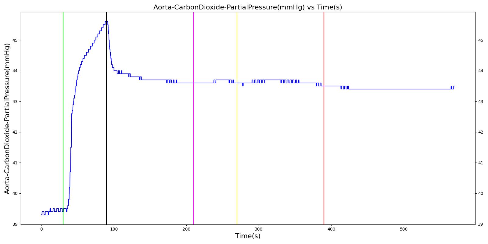
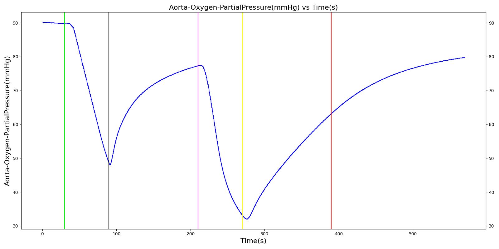
The oxygen wall pressure loss failure scenario begins by administering a neuromuscular blocker to cause a cessation of normal respiration. Mechanical ventilation then begins using a mask to supply the gas. Oxygen is supplied from the wall source, and the patient is stabilized. Then, oxygen wall port pressure source loss is triggered, and the physiological responses of the patient are observed. The process is repeated by turning the oxygen wall pressure loss condition on and off, followed by the use of the oxygen bottle tank as a source. The oxygen supply failure due to O2 wall pressure loss causes a drop in arterial oxygen level and a re-supply of oxygen by turning off the failure brings the oxygen level to normal.
 |  |
 |  |
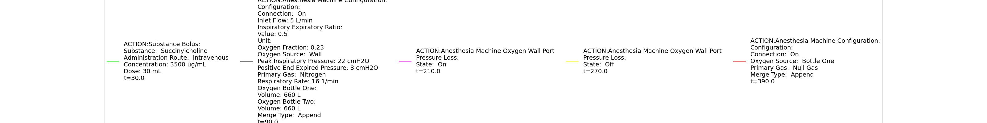 | |
Table 11 Validation matrix for physiological responses due to an oxygen wall pressure loss.
| Segment | Notes | Action Occurance Time (s) | Sampled Scenario Time (s) | Respiration Rate (breaths/min) | Oxygen Saturation | Tidal Volume (mL) | Aorta Oxygen Partial Pressure (mmHg) | Aorta Carbon Dioxide Partial Pressure (mmHg) |
|---|---|---|---|---|---|---|---|---|
| Administer succinycholine. | Neuromuscular blocker agent is injected and patient stops breathing. | 30 | 90 | Goes to Zero [127] Goes to Zero [269] | Begins to drop according to desaturation curve | Goes to Zero [127] | Begins to drop w/o respiration | Begins to increase w/o respiration |
| Turn on Anesthesia Machine. | Place maske. Use wall oxygen as oxygen source. | 90 | 210 | 16 from machine setting | Begins to increase with return of respiration | Patient Normal Volume | Begins to increase with respiration | Begins to decrease with respiration |
| Turn on oxygen wall port pressure loss. | 210 | 270 | No Change | Begins to drop according to desaturation curve [127] | No Change | Begins to decrease with lack of oxygen [127] | No significant change | |
| Turn off oxygen wall port pressure loss. | 270 | 390 | No Change | Begins to increase with return of oxygen supply [127] | No Change | Begins to increase with return of oxygen supply [127] | No significant change | |
| Switch from wall port to oxygen bottle. | 390 | 570 | No Change | Continues to increase with oxygen supply [127] | No Change | No Change | No significant change |
Oxygen Tank Pressure Loss
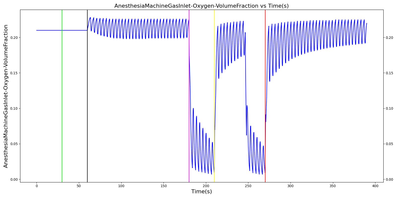
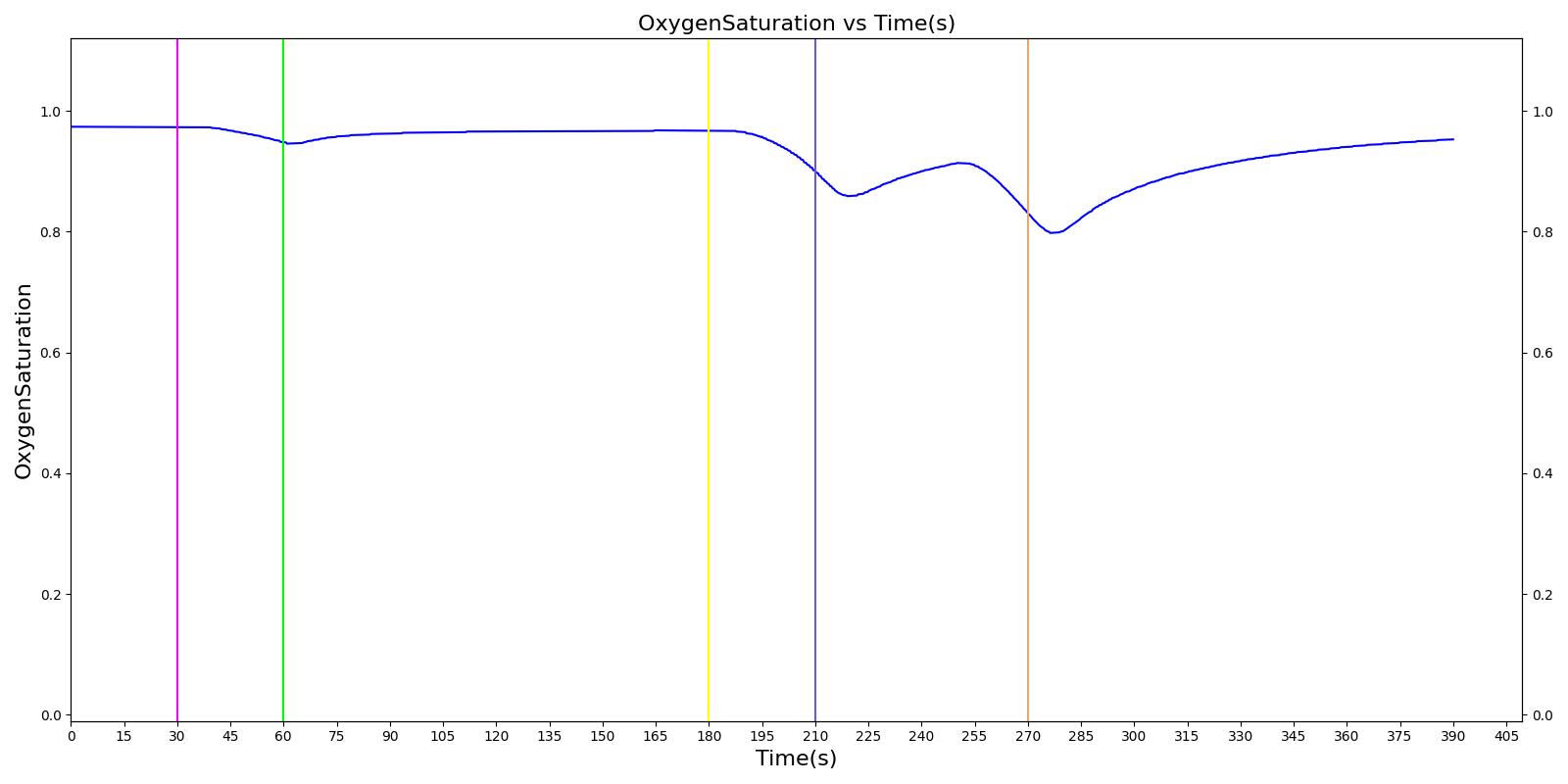
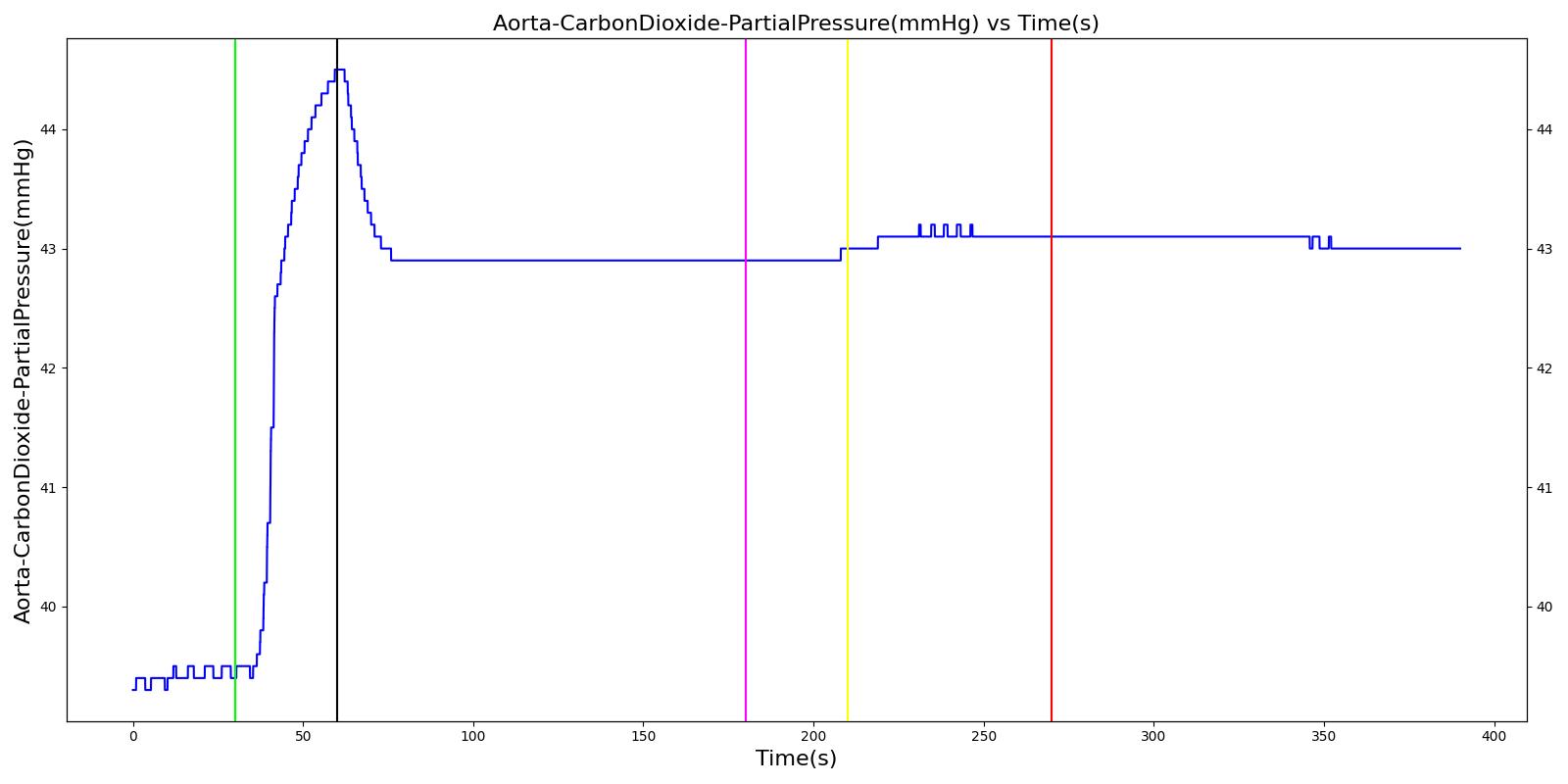
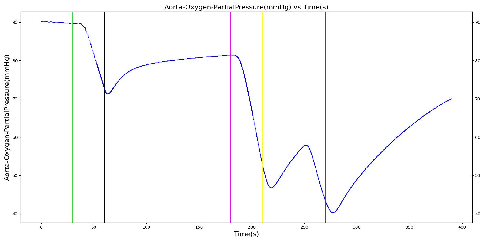
The Anesthesia System has two oxygen tanks as additional oxygen supply sources. Under normal conditions, the model allows selection between the two tanks as substitutes for the wall source. To address the effect of oxygen tank pressure loss, the model employs a scenario that begins by administering a neuromuscular blocker to disrupt normal respiration. Then, the Anesthesia Machine is turned on, and a mask is placed (similarly to the wall pressure loss scenario), but this time, the model uses an oxygen bottle tank as the oxygen source. The patient is stabilized first for some time. Then, the oxygen tank pressure loss event is triggered and the physiological responses of the patient are examined. The process is repeated by switching
the oxygen tank pressure loss state on and off and finally by replacing the original oxygen bottle tank with the second oxygen bottle tank in the model. The model responded well to the expected values and showed a decline in oxygen saturation and arterial oxygen partial pressure due to a failure in oxygen supply.
 |  |
 |  |
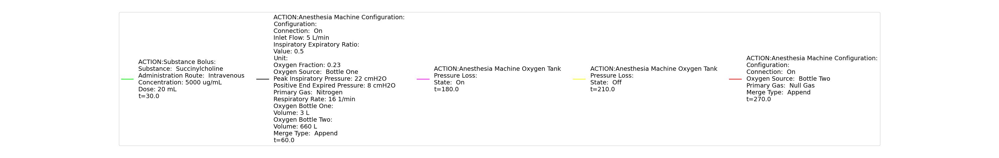 | |
Table 12 Validation matrix for physiological responses due to an oxygen tank pressure loss.
| Segment | Notes | Action Occurance Time (s) | Sampled Scenario Time (s) | Respiration Rate (breaths/min) | Oxygen Saturation | Tidal Volume (mL) | Aorta Oxygen Partial Pressure (mmHg) | Aorta Carbon Dioxide Partial Pressure (mmHg) |
|---|---|---|---|---|---|---|---|---|
| Administer succinycholine. | Neuromuscular blocker agent is injected and patient stops breathing. | 30 | 60 | Goes to Zero [127] Goes to Zero [269] | Begins to drop according to desaturation curve | Goes to Zero [127] | Begins to drop w/o respiration | Begins to increase w/o respiration |
| Turn on Anesthesia Machine. | Place maske. Use oxygen bottle tank as oxygen source. | 60 | 180 | 16 from machine setting | Begins to increase with return of respiration | Patient Normal Volume | Begins to increase with respiration | Begins to decrease with respiration |
| Turn on oxygen tank pressure loss. | 180 | 210 | No Change | Begins to drop according to desaturation curve [127] | No Change | Begins to decrease with lack of oxygen [127] | No significant change | |
| Turn off oxygen tank pressure loss. | 210 | 246 | No Change | Begins to increase with return of oxygen supply [127] | No Change | Begins to increase with return of oxygen supply [127] | No significant change | |
| Oxygen take runs out. | 246 | 270 | No Change | Begins to drop according to desaturation curve [127] | No Change | Begins to decrease with lack of oxygen [127] | No significant change | |
| Replace oxygen tank. | Use the second bottle. | 270 | 390 | No Change | Continues to increase with oxygen supply [127] | No Change | Begins to increase with return of oxygen supply [127] | No significant change |
Conclusion
While the model is a generic representation of mechanical ventilation and inhaled agent administration, this model represents the behavior of a complex piece of equipment that is associated with a difficult medical speciality. The engine provides a whole-body approach to modelling that allows for simulation of this complex field with multiple steps. This includes common equipment failures and the impacts they have on the body. This system is a strong addition to the engine with the potential for future development. This system has previously been used to power the training application HumanSim: Sedation and Airway, which was funded by TATRC under contract number W81XWH-11-C-0045.
Future Work
Coming Soon
There are no planned near term additions.
Recommended Improvements
The engine modularity could be taken advantage of to add parameters and elements for specific equipment models and manufacturers.
Further functionality to the Anesthesia Machine system includes the implementation of synchronized ventilation that allows spontaneous breathing along with positive-pressure ventilation, similar to the Mechanical Ventilator Methodology VC-AC functionality.
Appendices
Data Model Implementation
AnesthesiaMachineVaporizerFailure
AnesthesiaMachineConfiguration
AnesthesiaMachineOxygenTankPressureLoss
AnesthesiaMachineExpiratoryValveObstruction
AnesthesiaMachineInspiratoryValveLeak
AnesthesiaMachineSodaLimeFailure
AnesthesiaMachineExpiratoryValveLeak
AnesthesiaMachineInspiratoryValveObstruction
AnesthesiaMachineOxygenWallPortPressureLoss
AnesthesiaMachineVentilatorPressureLoss
AnesthesiaMachineYPieceDisconnect
Glossary
ETT - Endotracheal tube