
Overview
Abstract
We have designed and implemented a generic virtual extracorporeal membrane oxygenation (ECMO) device model into Pulse for real-time medical simulation. The ECMO methodology provides a configurable extracorporeal blood circuit with a membrane oxygenator for gas exchange, a blood pump, and an integrated fluid administration system. The device model connects dynamically to the existing Pulse cardiovascular system at configurable cannulation locations to support both venovenous (VV) and venoarterial (VA) configurations. Gas exchange across the membrane oxygenator is computed using a partial pressure gradient diffusion model driven by configurable sweep gas parameters. Proper functionality was validated against clinical data from patients receiving ECMO support, demonstrating accurate reproduction of oxygenation and decarboxylation responses across varied pump flows, sweep gas flows, and fraction of delivered oxygen settings.
Introduction
Extracorporeal Membrane Oxygenation
Extracorporeal membrane oxygenation (ECMO) is a form of extracorporeal life support (ECLS) that provides prolonged cardiac and/or respiratory support to patients whose heart and/or lungs are unable to provide adequate gas exchange or perfusion [237]. Blood is drained from the patient through a cannula, circulated through an external circuit by a centrifugal pump, passed through a membrane oxygenator where oxygen is added and carbon dioxide is removed, and then returned to the patient through a second cannula. The membrane oxygenator functions as an artificial lung, using a sweep gas (typically oxygen or an oxygen-air blend) flowing on one side of a semipermeable membrane while blood flows on the other, allowing gas exchange via diffusion along partial pressure gradients.
There are two primary ECMO configurations [381] :
- Venovenous (VV) ECMO: Blood is drained from and returned to the venous system. This configuration provides respiratory support only, as the native heart continues to provide all circulatory flow. VV ECMO is the preferred modality for isolated respiratory failure, such as severe acute respiratory distress syndrome (ARDS) [29].
- Venoarterial (VA) ECMO: Blood is drained from the venous system and returned to the arterial system. This configuration provides both cardiac and respiratory support, as the pump supplements or replaces native cardiac output.
Requirements
A robust Pulse ECMO device model is needed for several use cases, including clinical investigations, training simulators, and military medical simulation applications. The model required a generic representation of an extracorporeal blood circuit with gas exchange functionality that integrates with the existing Pulse cardiovascular fluid mechanics circuit and substance transport graph. A mechanistic modeling approach was employed to allow existing Pulse patient physiologies and pathophysiologies to be simulated with the addition of extracorporeal support. The ECMO model needed to support configurable cannulation sites for both VV and VA configurations, adjustable pump flow rates, sweep gas parameters for membrane oxygenator gas exchange, and an integrated fluid administration capability for volume resuscitation or blood product transfusion during ECMO support. Extensibility was required to interface with other Pulse equipment models (e.g., the mechanical ventilator) for combined life support scenarios.
System Design
Features and Capabilities
Circuit
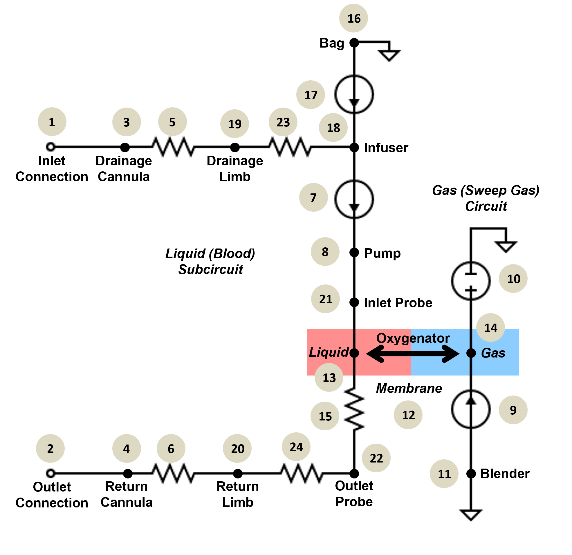
The ECMO device model consists of a dual-circuit architecture: a liquid (blood) circuit and a gas (sweep gas) circuit. The liquid circuit contains a centrifugal pump modeled as a flow source, drainage and return cannulae, tubing limbs, a membrane oxygenator liquid compartment, inlet and outlet monitoring probes, and a fluid administration bag with an infuser. The gas circuit contains a blender compartment for sweep gas composition and an oxygenator gas compartment. Figure 1 shows the ECMO liquid circuit diagram. The compartments and transport graph mirror the circuit. Substance values are transported through the circuit using the Pulse substance transporter. When the device is connected, the ECMO liquid circuit is added to the active cardiovascular circuit and solved as part of the combined linear algebra system.
Connecting to the Cardiovascular Circuit
When ECMO is applied to a patient, the extracorporeal circuit creates a parallel blood flow pathway that drains blood from and returns blood to the patient's vasculature. In the Pulse implementation, the ECMO liquid circuit is dynamically added to the active cardiovascular circuit at runtime. Circuit paths and compartment graph links are created between the cardiovascular nodes/compartments and the ECMO drainage and return cannula nodes/compartments based on the configured cannulation locations. The combined circuit is then solved as a single system, allowing bidirectional interaction between the native cardiovascular hemodynamics and the extracorporeal circuit.
Settings
The ECMO data model has been designed to provide a comprehensive set of configuration parameters that allow for simulation of varied ECMO configurations and operating conditions. The settings are organized into the following categories:
Cannulas
- 1. Inlet Location: Cannulation site for blood drainage from the patient
- 2. Outlet Location: Cannulation site for blood return to the patient
- 3. Drainage Cannula Volume
- 4. Return Cannula Volume
- 5. Drainage Cannula Resistance
- 6. Return Cannula Resistance
The following cannulation locations are supported, enabling both VV and VA configurations:
- Internal Jugular Vein
- Right Femoral Vein
- Left Femoral Vein
- Right Subclavian Vein
- Left Subclavian Vein
- Right Femoral Artery
- Left Femoral Artery
- Right Axillary Artery
- Left Axillary Artery
- Carotid Artery
- Right Atrium
- Ascending Aorta
- Superior Vena Cava
- Inferior Vena Cava
Several of these locations currently map to the same cardiovascular lumped parameter node/compartment due to the limited fidelity of that system in Pulse.
Pump
- 7. Pump Flow: Volumetric flow rate of the centrifugal pump (default: 3.0 L/min)
- 8. Pump Volume
Oxygenator
These settings control the membrane oxygenator gas exchange using a partial pressure gradient diffusion model. This is the primary and recommended mode of operation.
- 9. Sweep Gas Flow: Volumetric flow rate of the sweep gas through the oxygenator (default: 1.0 L/s)
- 10. Sweep Gas Pressure: Pressure of the sweep gas supply (default: ambient)
- 11. Fraction of Sweep Gas Oxygen (FdO2): Oxygen fraction in the sweep gas supply (0-1, default: 1.0)
- 12. Oxygen Membrane Diffusing Capacity: Diffusing capacity for oxygen across the membrane (default: 5.0 mL/s/mmHg)
- 12. Carbon Dioxide Membrane Diffusing Capacity: Diffusing capacity for carbon dioxide across the membrane (default: 10.0 mL/s/mmHg)
- 13. Oxygenator Liquid Volume
- 14. Oxygenator Gas Volume
- 15. Oxygenator Resistance
As an alternative to diffusion-based gas exchange, direct oxygen and carbon dioxide transfer rates can be specified. These settings cannot be used simultaneously with the diffusion mode parameters (9-12).
- Oxygen Rate: Direct volumetric rate of oxygen addition to blood in the oxygenator
- Carbon Dioxide Rate: Direct volumetric rate of carbon dioxide removal from blood in the oxygenator
Fluid Administration
- 16. Bag Compound: Substance compound for the infusion bag (e.g., Blood, Saline, PackedRBC; default: Blood)
- 16. Bag Volume: Initial volume of the infusion bag
- 17. Infuser Rate: Volumetric flow rate of fluid administration from the bag (default: 0.0 mL/s)
- 18. Infuser Volume
Peripherals
- 19. Drainage Limb Volume
- 20. Return Limb Volume
- 21. Inlet Probe Volume
- 21. Outlet Probe Volume
- 23. Drainage Limb Resistance
- 24. Return Limb Resistance
Actions
The ECMO model uses a single configuration action (SEExtracorporealMembraneOxygenationDeviceConfiguration) that supports both initial device connection and runtime parameter changes. The configuration action supports two merge modes:
- Replace: Clears existing settings and applies the new configuration
- Append: Merges new settings with existing settings, allowing individual parameters to be updated without resetting the entire configuration
The ECMO device can be disconnected by setting the inlet and/or outlet location to NullCannulationLocation.
Membrane Oxygenator Gas Exchange
The membrane oxygenator is the core functional element of the ECMO device, responsible for blood gas exchange. Two modes of operation are supported:
Diffusion Mode
In the primary diffusion mode, gas exchange is computed using a partial pressure gradient model across the membrane. For each gas species (O2 and CO2), the diffused volume per time-step is:
![\[{V_{diffused}}[mL] = \Delta P[mmHg] \times D_{L}[mL/s/mmHg] \times \Delta t[s]\]](form_98.png)
Where ΔP is the partial pressure gradient between the gas and liquid sides of the oxygenator, DL is the membrane diffusing capacity for the gas species, and Δt is the simulation time-step. The diffused volume is converted to mass using the substance density and transferred between compartments. Numerical safeguards prevent diffusion from exceeding the available substance quantity on either side of the membrane.
The sweep gas composition is determined by the blender compartment, which is set based on the configured FdO2. When FdO2 is 1.0 (pure medical-grade oxygen), the sweep gas contains no CO2. For blended air (FdO2 < 1.0), ambient CO2 fraction is used, and the remaining balance is nitrogen. The sweep gas circuit is solved independently each time-step, transporting gas through the oxygenator.
Rate Mode
In the alternative rate mode, oxygen and carbon dioxide transfer are specified as direct volumetric rates. Oxygen mass is added to the oxygenator liquid compartment and carbon dioxide mass is removed at the specified rates each time-step. This simplified mode is useful when the detailed sweep gas and membrane diffusion parameters are not needed or not known.
Data Flow
The ECMO model follows the same logic loop as all Pulse systems. The state at every time-step is determined through a three-step process:
PreProcess:
- Check for and process any ECMO configuration actions
- If cannulation locations have changed, perform a state change to connect/disconnect the circuit to/from the cardiovascular system
- Apply settings to update all circuit element values (pump flow, resistances, volumes)
- Perform oxygenator gas exchange (diffusion or rate-based)
- Calculate blood gas distribution for all ECMO compartments
- Calculate and set output parameters
Process:
- Solve the standalone gas circuit using the fluid circuit calculator
- Transport gas substances through the gas compartment graph
- The liquid circuit is solved as part of the combined cardiovascular circuit
PostProcess:
- Update gas circuit node volumes and pressures
Outputs
The ECMO device model calculates and exposes the following system output parameters:
| Output | Description |
|---|---|
| Blood Flow | Volumetric blood flow rate through the circuit (at the outlet probe) |
| Bag Volume | Current volume remaining in the fluid administration bag |
| Inlet Pressure | Blood pressure at the inlet monitoring probe |
| Outlet Pressure | Blood pressure at the outlet monitoring probe |
| Transmembrane Pressure Gradient | Pressure difference between inlet and outlet probes |
| Drainage Pressure | Blood pressure in the drainage limb |
| Inlet Oxygen Saturation | Oxygen saturation of blood entering the oxygenator |
| Outlet Oxygen Saturation | Oxygen saturation of blood exiting the oxygenator |
| Hemoglobin Concentration | Hemoglobin concentration in the drainage limb |
| Sweep Gas Flow | Volumetric flow rate of sweep gas through the oxygenator |
| Hydraulic Transmembrane Pressure Gradient | Pressure difference between oxygenator gas and liquid sides |
| Membrane Lung Oxygen Contribution | Rate of oxygen transfer by the membrane oxygenator |
| Membrane Lung Carbon Dioxide Contribution | Rate of carbon dioxide removal by the membrane oxygenator |
Dependencies
The ECMO device interacts primarily with the Cardiovascular System through dynamic circuit connections that drain and return blood at the configured cannulation sites. The two systems are combined into a single circuit at runtime, allowing the ECMO pump flow to directly influence cardiovascular hemodynamics (e.g., venous pressures, cardiac output). The ECMO device is also responsive to the flow resistances and pressures of the cardiovascular system.
The ECMO device substance transport is integrated with the active cardiovascular compartment graph. Blood substance concentrations (oxygen, carbon dioxide, hemoglobin species) are exchanged bidirectionally between the ECMO compartments and the cardiovascular compartments at the inlet and outlet connection points.
The ECMO device is commonly used in conjunction with the Mechanical Ventilator (see Mechanical Ventilator Methodology) for combined respiratory support of patients with severe ARDS. The ECMO oxygenator supplements the patient's native lung gas exchange, while the mechanical ventilator provides positive pressure ventilation.
The ECMO device is linked to the Environment System that regulates the atmospheric/reference pressure. Ambient gas fractions are used for sweep gas blending when FdO2 is less than 1.0.
Assumptions and Limitations
The current ECMO implementation uses an ideal flow source for the centrifugal pump. The pump does not model pressure-flow characteristics of real centrifugal pumps, where delivered flow depends on the pressure differential across the pump head. All valves are ideal and do not allow backflow.
The membrane oxygenator gas exchange model uses a simplified single-compartment partial pressure gradient diffusion. It does not model the spatial distribution of gas exchange along the membrane fiber bundle, membrane fouling or degradation over time, or temperature-dependent gas solubility effects. The diffusing capacity parameters are assumed constant throughout the simulation.
Recirculation in VV ECMO (where oxygenated blood returned to the venous system is re-drained by the drainage cannula before reaching the patient's lungs) is modeled implicitly through the shared cardiovascular circuit nodes, but the degree of recirculation depends on the fidelity of the cardiovascular circuit topology between the cannulation sites.
The fluid administration system uses an ideal infusion model where the bag compound is delivered at the specified rate until the bag is depleted.
Currently, the ECMO model does not simulate anticoagulation requirements, circuit thrombosis, hemolysis, or other complications associated with prolonged ECMO support.
Results and Conclusions
Validation - Automated Scenarios
The following automated validation scenarios are executed as part of the Pulse test suite. Each scenario configures a patient with specific pathophysiology and applies ECMO support with defined settings. Validation tables compare simulation outputs against expected values, and monitor plots show the temporal evolution of key physiological parameters.
Extracorporeal Membrane Oxygenation Device Validation
Validation - Digital Twins
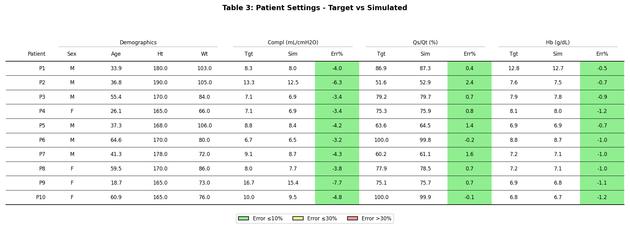
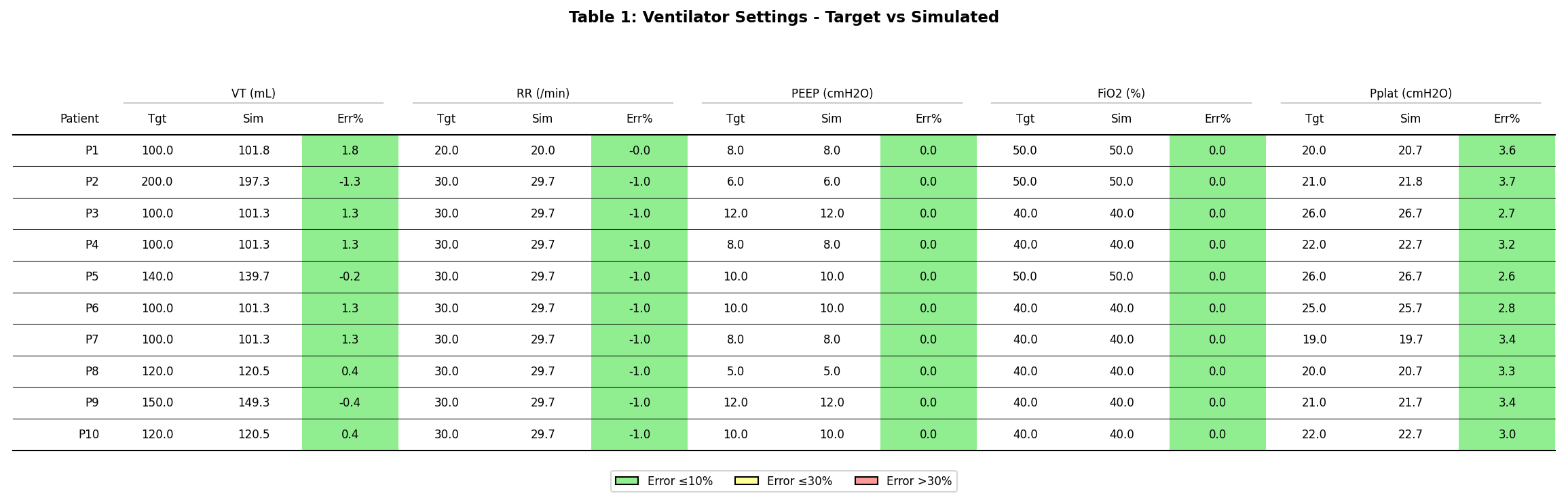
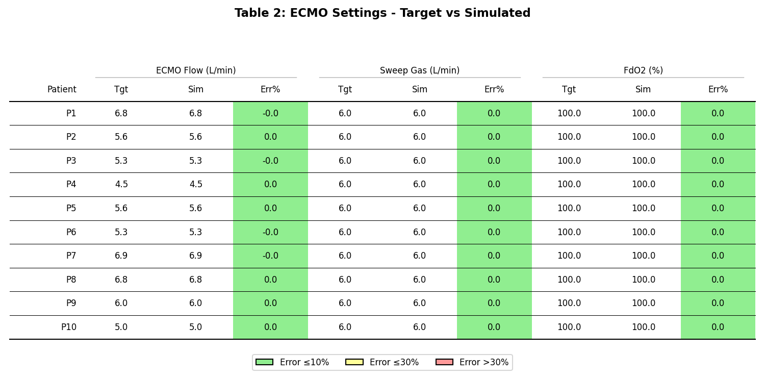
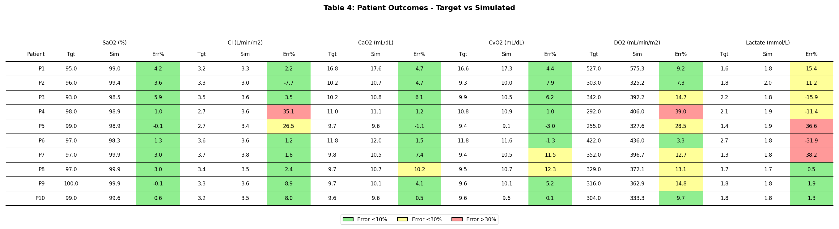
To further validate the ECMO model's gas exchange functionality, we replicated the clinical study by Schmidt et al. [346], which investigated blood oxygenation and decarboxylation determinants during venovenous ECMO for respiratory failure in adults. The study included 10 mechanically ventilated ARDS patients receiving femoro-jugular VV ECMO support. We created individual digital twin models for each patient, matching their respiratory compliance, intrapulmonary shunt fraction, hemoglobin concentration, ECMO settings, and ventilator settings. Three experimental protocols were then simulated, varying pump flow, sweep gas flow, and FdO2 independently while holding other parameters at their maximum clinical values.
Patient Configuration
Each digital twin was configured with patient-specific respiratory mechanics (lung compliance), gas exchange impairment (intrapulmonary shunt fraction), and blood properties (hemoglobin concentration) derived from the clinical data. Mechanical ventilation was applied with patient-specific tidal volume, respiratory rate, PEEP, FiO2, and plateau pressure settings.
Patient Outcomes
The following table compares baseline steady-state patient outcomes between the clinical study and the Pulse digital twins. Key parameters include arterial oxygen saturation (SaO2), cardiac index (CI), arterial and venous oxygen content (CaO2, CvO2), oxygen delivery (DO2), and lactate levels.
Pump Flow Protocol
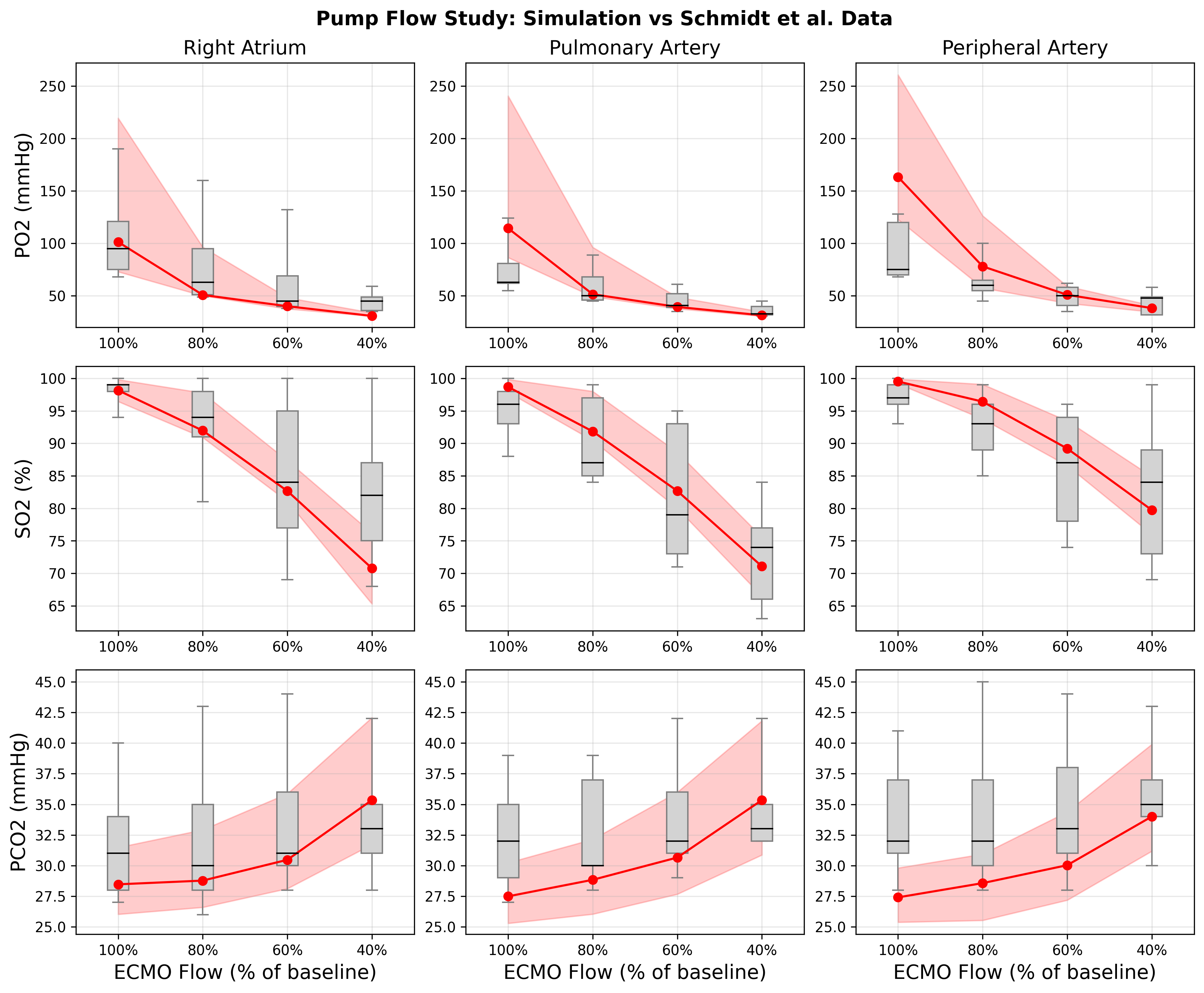
The pump flow protocol varied ECMO circuit blood flow from 40% to 100% of the maximum clinically used flow rate for each patient, with sweep gas flow and FdO2 held at their maximum values. The clinical study measured arterial PO2, SaO2, and PCO2 at each flow level. The Pulse simulation results show the model correctly reproduces the expected dose-response relationship: increasing pump flow increases oxygenation (PO2/SaO2) and CO2 removal across all patients.
Sweep Gas Flow Protocol
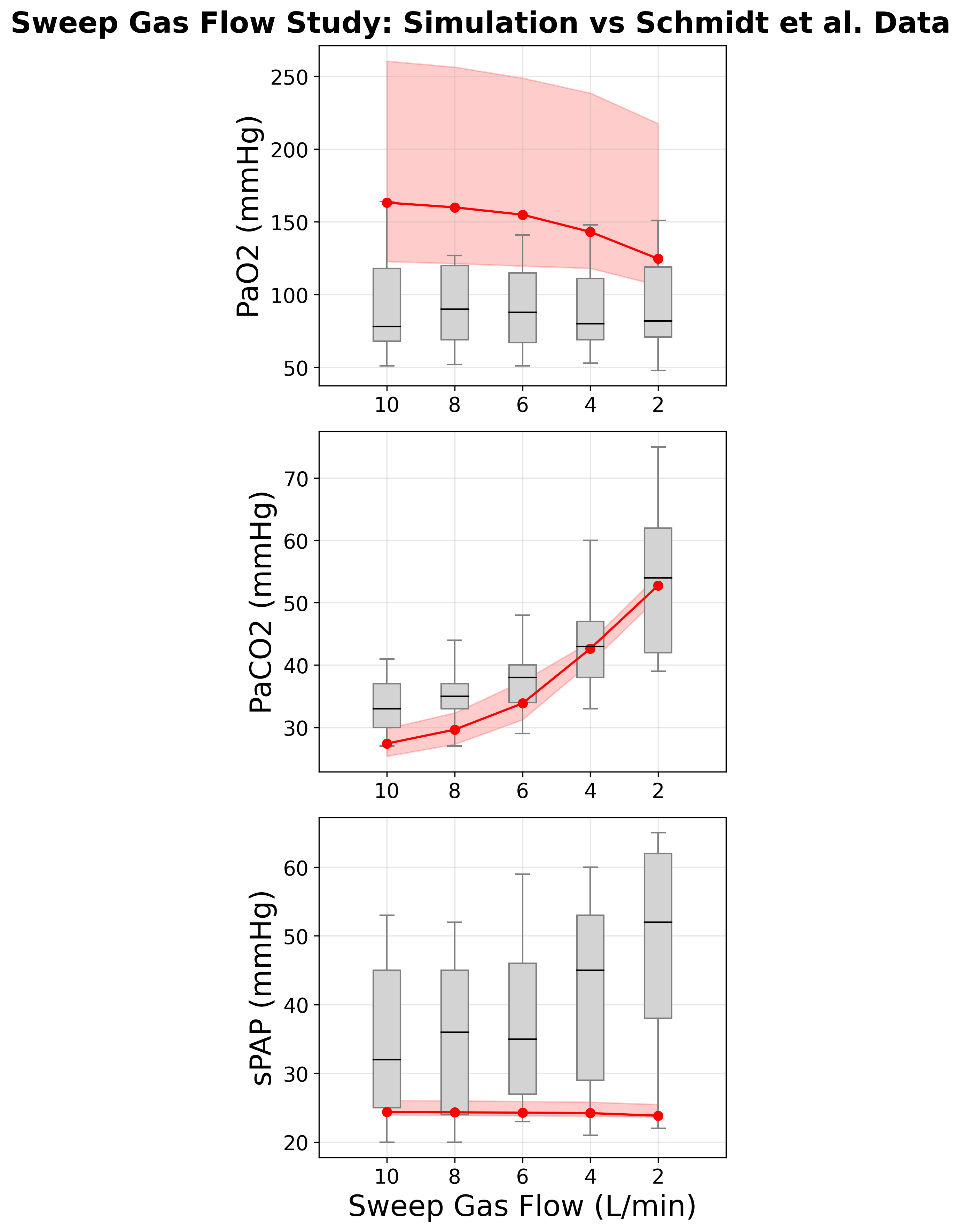
The sweep gas flow protocol varied the sweep gas flow rate from 2 to 10 L/min while pump flow and FdO2 were held at maximum. Sweep gas flow is the primary determinant of CO2 removal across the membrane oxygenator. The Pulse simulation results demonstrate the expected strong dose-dependent response: increasing sweep gas flow dramatically decreases arterial PCO2 (from approximately 70 mmHg at 2 L/min to approximately 25 mmHg at 10 L/min), consistent with the clinical observations.
FdO2 Protocol
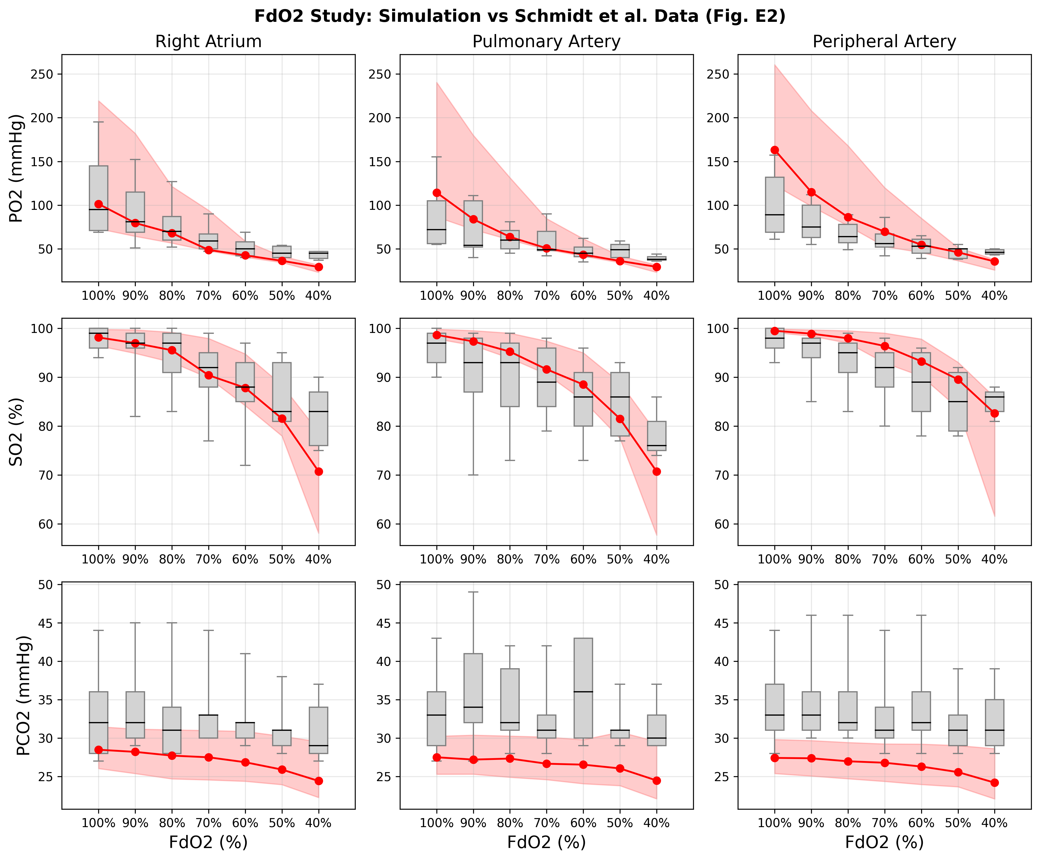
The FdO2 protocol varied the fraction of delivered oxygen in the sweep gas from 40% to 100% while pump flow and sweep gas flow were held at maximum. The Pulse simulation results show the model correctly reproduces the dose-response: increasing FdO2 increases arterial and venous PO2 and oxygen saturation. The response plateaus at high FdO2 levels due to the sigmoidal shape of the oxygen-hemoglobin dissociation curve.
Conclusion
The Pulse ECMO device model provides a comprehensive, configurable simulation of extracorporeal membrane oxygenation with physiologically-based gas exchange. The model supports both VV and VA configurations through flexible cannulation site selection and integrates seamlessly with the existing Pulse cardiovascular and respiratory systems. Validation against the Schmidt et al. clinical study demonstrates that the model accurately reproduces the key determinants of blood oxygenation and decarboxylation during VV ECMO, including the dose-response relationships for pump flow, sweep gas flow, and fraction of delivered oxygen. The ECMO model, combined with the Pulse mechanical ventilator, enables simulation of comprehensive life support scenarios for critically ill patients, including severe ARDS management and trauma resuscitation with extracorporeal support.
Future Work
Coming Soon
Integration of ECMO-specific complication modeling, including circuit thrombosis and hemolysis indicators.
Recommended Improvements
- Implementation of pressure-flow characteristics for the centrifugal pump to model afterload-dependent flow delivery.
- Spatially-distributed membrane oxygenator model to capture fiber bundle geometry effects on gas exchange efficiency.
- Temperature management modeling for ECMO heat exchangers.
- Recirculation fraction estimation and reporting for VV ECMO configurations.
- Anticoagulation modeling for circuit management.
Appendices
Data Model Implementation
Extracorporeal Membrane Oxygenation Device
Glossary
ARDS - Acute Respiratory Distress Syndrome
CaO2 - Arterial Oxygen Content
CI - Cardiac Index
CO2 - Carbon Dioxide
CvO2 - Venous Oxygen Content
DO2 - Oxygen Delivery
ECLS - Extracorporeal Life Support
ECMO - Extracorporeal Membrane Oxygenation
ELSO - Extracorporeal Life Support Organization
FdO2 - Fraction of Delivered Oxygen
FiO2 - Fraction of Inspired Oxygen
IJ - Internal Jugular
IVC - Inferior Vena Cava
O2 - Oxygen
PaCO2 - Arterial Carbon Dioxide Partial Pressure
PaO2 - Arterial Oxygen Partial Pressure
PCO2 - Carbon Dioxide Partial Pressure
PEEP - Positive End Expired Pressure
PO2 - Oxygen Partial Pressure
SaO2 - Arterial Oxygen Saturation
SO2 - Oxygen Saturation
SPAP - Systolic Pulmonary Artery Pressure
VA - Venoarterial
VV - Venovenous